SLIA086A June 2014 – December 2021 DRV5013 , DRV5013-Q1 , DRV5023 , DRV5023-Q1 , DRV5033 , DRV5033-Q1 , DRV5053 , DRV5053-Q1
5 Linear Hall Sensor Functionality
TI’s analog Hall sensors such as the DRV5055 have an analog voltage output that changes proportionally with the magnetic field.
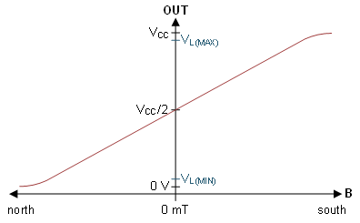
 Figure 5-1 B-field Response of the DRV5055
The device uses a ratiometric architecture that can help remove error due to VCC tolerance when the external analog-to-digital converter (ADC) uses the same VCC for its reference. When no magnet is present (B = 0), the output voltage is VQ , which is around VCC/2. The presence of a magnetic field scales the output toward VCC or 0 V.
| PARAMETER | MIN | TYP | MAX | UNIT | |
|---|---|---|---|---|---|
| VQ | Quiescent output at VCC=5 V | 2.43 | 2.5 | 2.57 | V |
| Quiescent output at VCC=3.3 V | 1.59 | 1.65 | 1.71 | ||
| VL | Linear range of output voltage | 0.2 | VCC-0.2 | ||
The usable voltage range of this device is between 0.2 V and VCC-0.2 V because the B-response becomes nonlinear close to the rails.
The slope of the response is known as sensitivity, and measured in units of mV/mT. For ratiometric devices, this sensitivity is dependent on the VCC voltage. Using the DRV5055A1 when VCC=5 V as an example, typical sensitivity is 100mV/mT, meaning a B-field of 2 mT typically shifts the output by 0.2 V from VCC/2. If VCC is 5 V, that means the output would be 2.7 V. B-field >23 mT saturates the DRV5055A1, since the output drops below 0.2 V.
| PARAMETER | MIN | TYP | MAX | UNIT | ||
|---|---|---|---|---|---|---|
| DRV5055A1/Z1 | S | Sensitivity | 95 | 100 | 105 | mV/mT |
| BL |
Linear magnetic sensing range |
±21 | mT | |||
| DRV5055A2/Z2 | S | Sensitivity | 47.5 | 50 | 52.5 | mV/mT |
| BL | Linear magnetic sensing range | ±42 | mT | |||
| DRV5055A3/Z2 | S | Sensitivity | 23.8 | 25 | 26.2 | mV/mT |
| BL | Linear magnetic sensing range | ±85 | mT | |||
| DRV5055A4/Z4 | S | Sensitivity | 11.9 | 12.5 | 13.2 | mV/mT |
| BL | Linear magnetic sensing range | ±169 | mT | |||
| PARAMETER | MIN | TYP | MAX | UNIT | ||
|---|---|---|---|---|---|---|
| DRV5055A1/Z1 | S | Sensitivity | 57 | 60 | 63 | mV/mT |
| BL |
Linear magnetic sensing range |
±22 | mT | |||
| DRV5055A2/Z2 | S | Sensitivity | 28.5 | 30 | 31.5 | mV/mT |
| BL | Linear magnetic sensing range | ±44 | mT | |||
| DRV5055A3/Z2 | S | Sensitivity | 14.3 | 15 | 15.8 | mV/mT |
| BL | Linear magnetic sensing range | ±88 | mT | |||
| DRV5055A4/Z4 | S | Sensitivity | 7.1 | 7.5 | 7.9 | mV/mT |
| BL | Linear magnetic sensing range | ±176 | mT | |||
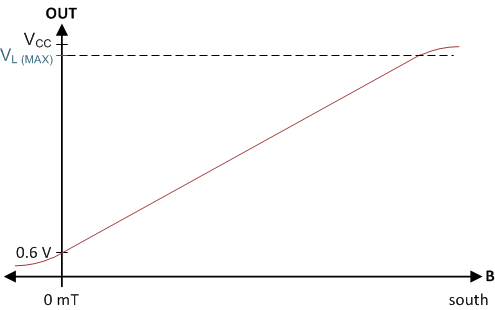
The DRV5055 is a bipolar Hall position sensor, which means that it responds to both positive and negative fields. If the sensed magnetic flux density is only positive, the DRV5056 device can also be used in applications. The DRV5056 is a unipolar ratiometeric Hall sensor that only responds to positive fields. Since unipolar sensors only sense one polarity, the DRV5056 has more sensing resolution compared to the DRV5056; however, since bipolar devices work with both poles of a magnet,the DRV5055 allows the magnet to be placed without determining whether a pole of the magnet is the south or north pole.
 Figure 5-2 B-field Response of the DRV5056
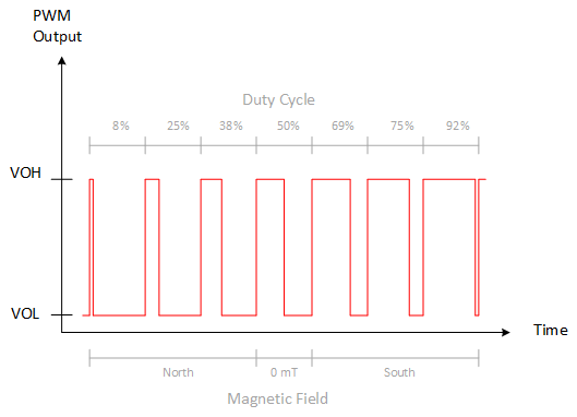
As an alternative to analog output Hall sensors, a Hall sensor with a PWM circuit like the DRV5057 can also be used. For PWM output devices, the duty cycle ratio of the output pulse varies based on the sensed magnetic flux density. A PWM output provides more immunity to external noise.
 Figure 5-3 B-field Response of the DRV5057
Additionally, Hall-effect sensors with a digital communication interface like SPI or I2C is available. Example devices for this interface include the TMAG5170 (SPI) and TMAG5273 (I2C) linear 3D Hall-effect sensors.