SLAAE57 June 2022 TAS2563
4.1 Tuning and Audio Processing
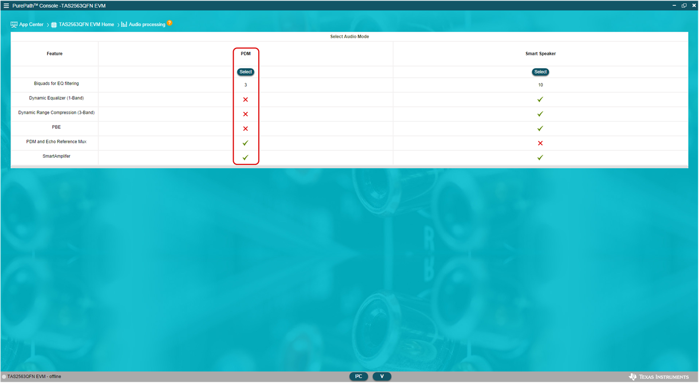
When creating a new PPC3 tuning file, first go to the tuning and audio processing panel. The reason for this is that either PDM or smart amp only configuration must be selected. This use-case covers the PDM mode.
 Figure 4-1 Audio Modes
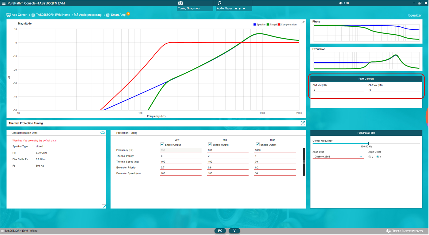
Once PDM is selected, the smart amp panel can be used to access the PDM microphone gain settings.
 Figure 4-2 PDM Microphone Gain
In addition, the output data selection is available in two different options:
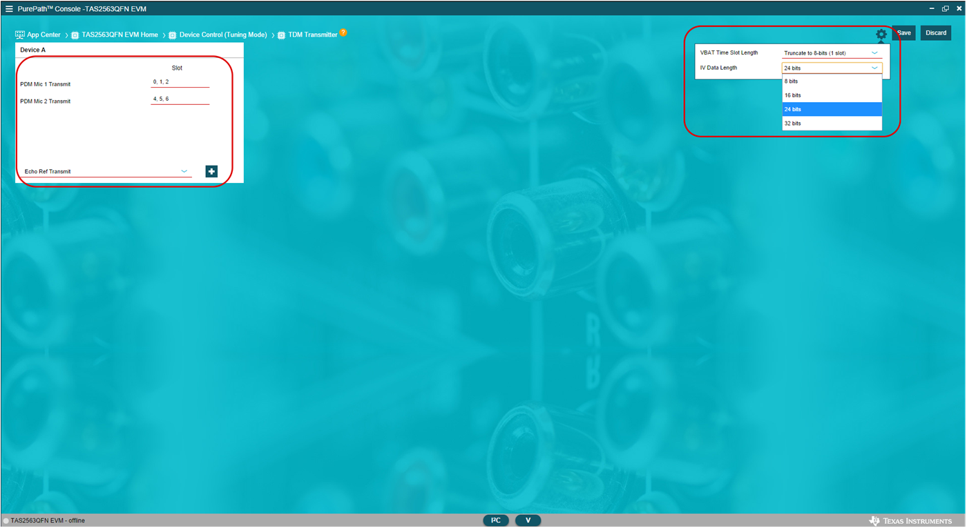
- At Device Control -> TDM Transmitter
-> Configure Slots device control panel -> transmitter -> configure slots.
Here the device can be configured as part of debugging on the EVM. Different types
of data can be included and the gear icon on the top right corner allows the user to
select the data length.
 Figure 4-3 SDOUT Data Configuration -
Device Control
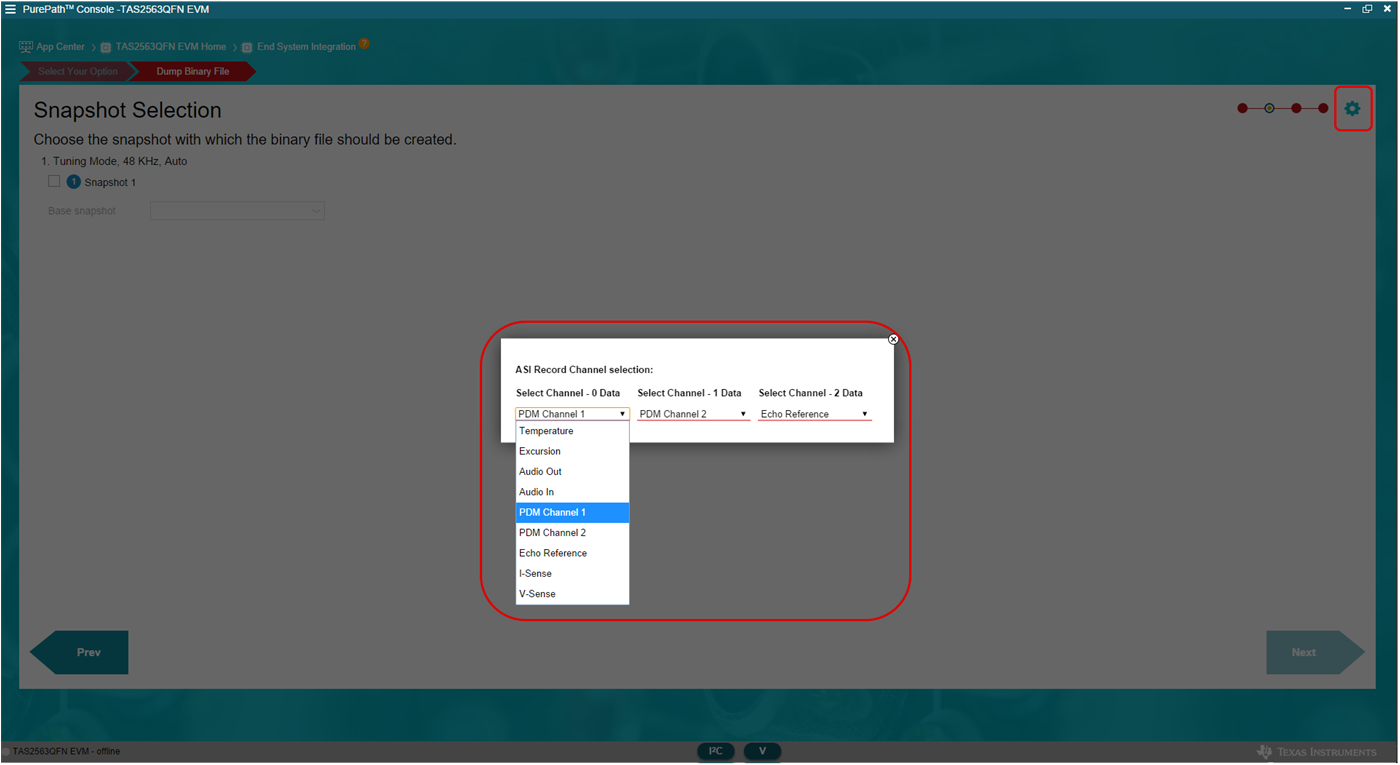
 - This can also be configured at the end-system integration, as part of the snapshot
selection configuration. Use the gear icon on the top right corner to access the
different output data options.
 Figure 4-4 SDOUT Data Configuration -
End System Integration