SLAA889A March 2019 – July 2021 MSP430FR6041 , MSP430FR6043 , MSP430FR60431 , MSP430FR6045 , MSP430FR6047 , MSP430FR60471
2.2.1.1 Acquisition Algorithm for AbsTOF
As mentioned above, the acquisition algorithm is run when there is no previous memory of the AbsTOF value or when the algorithm detects an anomaly in two consecutive measurements of AbsTOF. Figure 2-5 shows a representative captured ADC waveform. The small circles in this figure represent the captured points.
 Figure 2-5 Representative Captured Waveform
As given in Equation 8, i is the time index for the signal capture and
 is the upstream captured signal.
The acquisition algorithm then employs the following steps:
- For every i equal to 2 to (N – 1), let i = {i1, i2, ..., iM } for which
 .
.
This means the central value
 is greater than or equal to the two points on either side. The algorithm then uses parabolic interpolation between the
 for all such i. A parabolic interpolation is chosen (rather than the cosine interpolation for dTOF calculation) for reduced complexity, and the accuracy on AbsTOF estimation is not as tight as the dTOF estimation in terms of contribution to the overall flow error. The algorithm tabulates all these interpolated values. Letting
  denote the interpolated value these tabulated values can be given by
 . These interpolated values would now correspond to the "maximum of lobe" values of each wave in Figure 2-5. These are shown by dark red dots in Figure 2-6 and Figure 2-7.
 - The algorithm then computes the maximum over all these tabulated values
. This thus generates the maximum of the signal. Let this maximum of the signal be denoted by
 .
. - Let η denote the threshold for the wave lobe that we would like the AbsTOF algorithm to lock on to. This threshold would be a function of the type of transducers and should be set to a value where we expect the maximum rate of the change of the waveform. This threshold is typically set to 0.1 in the USS Software Library. Then let
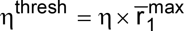 . This threshold can be controlled using the #define USS_ALG_RATIO_OF_TRACK_LOBE in USS_userConfig.h and maintained in USS_Algorithms_User_Configuration. ratioOfTrackLobeToPeak.
 - For the tabulated interpolated values
, find that value of i = iK for which the tabulated value is closest to ηthresh that is the
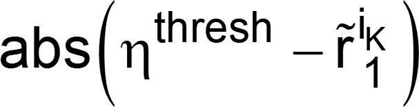 is minimum. The offset delay of the maximum from index iK is then calculated from the parabolic interpolation equation.
The value iK would now be used as an index for the next signal capture. Figure 2-6 and Figure 2-7 show the acquisition process.
 Figure 2-6 Interpolation in Acquisition Algorithm of AbsTOF
 Figure 2-7 Data Points for Acquisition Algorithm for AbsTOF