SLAA398A September 2008 – August 2018 MSP430F4794 , MSP430F4794
4 MSP430 + Charge Pump Implementation for Single-Cell Thermostat
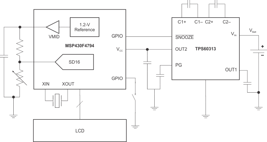
The MSP430 + charge pump implementation is shown on the next page. The only external components required for the charge pump circuit are five 1-µF ceramic capacitors. The SNOOZE pin is connected to one of the MSP430’s GPIO pins. In the event that higher current (more than 2 mA) is required, the charge pump automatically exits snooze mode but, in the case of an A/D conversion, it is best practice to disable SNOOZE in software by setting the appropriate MSP430 pin high before the conversion is initiated.
 Figure 4. MSP430F4794 and TPS60313 Block Diagram