SBOU272 November   2021 INA2126 , INA2128


  1.   Trademarks
  2. 1Overview
    1. 1.1 Features
    2. 1.2 INA Pinout
    3. 1.3 Compatible Devices
  3. 2Quick Start
    1. 2.1 Dual-Supply Configuration
    2. 2.2 Single-Supply Configuration
      1. 2.2.1 Direct Reference Connection
      2. 2.2.2 Buffered-Reference Voltage Connection
  4. 3EVM Components
    1. 3.1 Power
    2. 3.2 Inputs
      1. 3.2.1 Input Filtering
    3. 3.3 Output
      1. 3.3.1 Output Filtering
    4. 3.4 Reference
    5. 3.5 Miscellaneous
  5. 4Schematic, PCB Layout, and Bill of Materials
    1. 4.1 Schematic
    2. 4.2 PCB Layout
    3. 4.3 Bill of Materials

Input Filtering

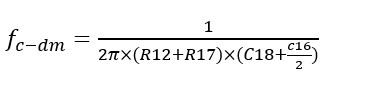
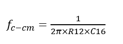
Components R12, R17, and C16, C18, C21 provide the ability to apply common-mode and differential-mode filtering to the inputs. The cutoff frequencies for the filters are shown in Equation 1 and Equation 2. Make C18 approximately ten times larger than C16 and C21. These calculations presume R12 = R17 and C16 = C21. The correlating resistors and capacitors provide input filtering for channel B.

Common-mode cutoff frequency:

Equation 1. GUID-20210804-CA0I-CXJ1-BV5B-8NNNVFLNNP2V-low.png

Differential-mode cutoff frequency:

Equation 2. GUID-20210804-CA0I-LDHJ-J8VF-XFWKGR1XZ2P2-low.png