SBAU375 November 2021
2.2 Comparator Outputs
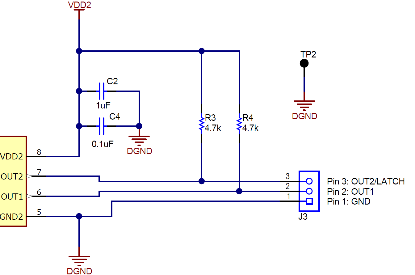
The comparator outputs are accessible on the three-wire screw terminal J3 on pins 2 and 3. Table 2-1 lists the pin connections to the J3 screw terminal for each of the AMC23Cxx devices.
| Device | J3.2 | J3.3 |
|---|---|---|
| AMC23C14 | OUT1 (open-drain) | OUT2 (open-drain) |
| AMC23C12 | OUT (open-drain) | LATCH (input) |
| AMC23C11 | OUT1 (open-drain) | LATCH (input) |
| AMC23C10 | OUT1 (open-drain) | OUT2 (push-pull) |
Depending on the isolated comparator device, each output may be an open-drain or push-pull configuration. The OUT1/OUT pin is open-drain in all cases, and the 4.7-kΩ resistor R4 is used to pull the output up to VDD2. For the AMC23C11EVM and the AMC23C12EVM, the OUT2/LATCH pin is an input and the pullup resistor R3 is left unpopulated. For the AMC23C10EVM, the OUT2/LATCH pin is a push-pull output, with no pullup resistor populated on R3. For the AMC23C14EVM, the OUT2 pin is an open-drain output, and R3 is populated with a 4.7-kΩ resistor pulling the pin up to VDD2.
Figure 2-2 shows the comparator output section of the AMC23CxxEVM schematic.
 Figure 2-2 AMC23CxxEVM Schematic: Comparator Output Section