SBAA517 June 2021
2 Background
JESD204B was the successor to the A standard, which lacked the means to synchronize multiple collocated devices. In other words, if you had two identical data converters on a circuit card assembly and wanted the inputs (or outputs) to be phase-coherent, then you could not use the A standard – it simply did not support any means to accomplish this. The B standard introduced the concept of sub-classification, which provided a backward-compatibility mode (subclass 0) along with two new classes (1 and 2) that provided deterministic latency between the sample time and the data arrival in the consumer (such as an FPGA).
JESD204A was much slower than the B revision. The original standard had a maximum lane rate of 3.125 Gbps, while the B standard was capable of up to 12.5 Gbps. As these lane rates increased, it introduced issues that are common with high-speed serial links: signal integrity, clock recovery and base line wander. Base line wander is a phenomenon caused by an unequal number of 1s and 0s on a transmission line, causing the dielectric to charge and the DC center point of the transmission line to move. This movement can cause two significant issues: it can introduce jitter as well as coding errors.
Base line wander most commonly occurs in systems that are AC-coupled. The AC-coupling is used to mitigate DC offsets between the transmitter and the receiver.
To mitigate base line wander and provide a means for AC coupling, the original standard used 8B/10B symbol encoding. For those not familiar with this type of coding, it is a simple lookup table that returns a 10-bit “symbol” for every octet (8-bit word). 8B/10B symbol encoding also introduces other clever techniques to overcome the running disparity of 1s and 0s and maintain a fixed DC point on the line, while always providing transitions to bridge-coupling capacitors.
Some additional symbols are not used for data but rather for in-band signaling to the receiver. For example, the K28.5 (comma) symbol is used for lane alignment, so at startup, the receiver can establish where in the stream the bits begin (for example, to find the start of a symbol frame). Once the receiver establishes the connection, it can signal back (through the SYNC signal) that the receiver is now matching the encoder, and data traffic can begin.
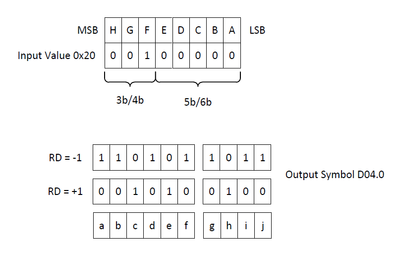
8B/10B coding is an excellent method for the task of serialization and deserialization, but it adds a 20% penalty to the capacity of each lane (channel). So for every 8 bits of data provided by the sender, 10 bits are actually transmitted (see Figure 2-1 as an example). As data capacity increases, 8B/10B coding becomes greatly inefficient.
Another side effect of serialization and extremely fast lanes is noise injection, which is a byproduct of 8B/10B encoding along with the high-speed transmission lines. Repetitive symbols that couple to the input (or output) of data converters may appear as spectral spurs, which can affect system performance. JESD204 provides a scrambling polynomial that can be turned on once the link is established to spread the energy and lower the spurious content.
 Figure 2-1 Shown is an Example of 8B/10B Coding in Which 8-Bit Value 0x20 is Encoded to the D.04.0 10-Bit Symbol
As with any serialization methodology, data from multiple sources can be multiplexed into several lanes and reconstructed on the other end. In the International Organization for Standardization Open System Interconnection (ISO-OSI) model, the interface is broken into several layers: the transport, data link and physical layers. The data-link layer performs much of the aforementioned encoding and decoding, but data multiplexing takes place in the transport layer before encoding, which is one of the most complex blocks in the JESD204 standard. This block fundamentally allows the transporting of multiple converter channels across multiple serialized lanes. Multiple channels on individual data converters will be phase coherent, but the delay of the transport layer will vary for various reasons. JESD204B added a mechanism to provide deterministic latency so that multiple devices can be made phase coherent which is very important for electronically steered arrays (ESA).