ZHCSBJ1B August   2013  – August  2015 UCC27517A-Q1

PRODUCTION DATA.  

  1. 特性
  2. 应用范围
  3. 说明
  4. 修订历史记录
  5. Description (continued)
  6. Device Comparison Table
  7. Pin Configuration and Functions
  8. Specifications
    1. 8.1 Absolute Maximum Ratings
    2. 8.2 ESD Ratings
    3. 8.3 Recommended Operating Conditions
    4. 8.4 Thermal Information
    5. 8.5 Electrical Characteristics
    6. 8.6 Switching Characteristics
    7. 8.7 Typical Characteristics
  9. Detailed Description
    1. 9.1 Overview
    2. 9.2 Functional Block Diagram
    3. 9.3 Feature Description
      1. 9.3.1 VDD and Undervoltage Lockout
      2. 9.3.2 Operating Supply Current
      3. 9.3.3 Input Stage
      4. 9.3.4 Enable Function
      5. 9.3.5 Output Stage
      6. 9.3.6 Low Propagation Delays
    4. 9.4 Device Functional Modes
  10. 10Application and Implementation
    1. 10.1 Application Information
    2. 10.2 Typical Application
      1. 10.2.1 Design Requirements
      2. 10.2.2 Detailed Design Procedure
        1. 10.2.2.1 Input-to-Output Logic
        2. 10.2.2.2 Input Threshold Type
        3. 10.2.2.3 VDD Bias Supply Voltage
        4. 10.2.2.4 Peak Source and Sink Currents
        5. 10.2.2.5 Enable and Disable Runction
        6. 10.2.2.6 Propagation Delay
      3. 10.2.3 Application Curves
  11. 11Power Supply Recommendations
  12. 12Layout
    1. 12.1 Layout Guidelines
    2. 12.2 Layout Example
    3. 12.3 Thermal Considerations
    4. 12.4 Power Dissipation
  13. 13器件和文档支持
    1. 13.1 社区资源
    2. 13.2 商标
    3. 13.3 静电放电警告
    4. 13.4 Glossary
  14. 14机械、封装和可订购信息

封装选项

请参考 PDF 数据表获取器件具体的封装图。

机械数据 (封装 | 引脚)
  • DBV|5
散热焊盘机械数据 (封装 | 引脚)
订购信息

7 Pin Configuration and Functions

DBV Package
5-Pin SOT-23
Top View
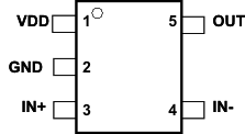
UCC27517A-Q1 pin_lusay4.gif

Pin Functions

PIN I/O DESCRIPTION
NO. NAME
1 VDD I Bias supply input
2 GND Ground. All signals reference to this pin
3 IN+ I Non-inverting input. Apply PWM control signal to this pin when driver is desired to be operated in non-inverting configuration. When the driver is used in inverting configuration, connect IN+ to VDD in order to enable output, OUT held LOW if IN+ is unbiased or floating
4 IN– I Inverting input. Apply PWM control signal to this pin when driver is desired to be operated in inverting configuration. When the driver is used in non-inverting configuration, connect IN– to GND in order to enable output, OUT held LOW if IN– is unbiased or floating
5 OUT O Sourcing/Sinking current output of driver