ZHCSCH9 May 2014 TRF37D73
PRODUCTION DATA.
8 Applications and Implementation
8.1 Application Information
The TRF37D73 is a wideband, high performance, general purpose RF amplifier. To maximize its performance, good RF layout and grounding techniques should be employed.
8.2 Typical Application
The TRF37D73 device is typically placed in a system as illustrated in Figure 13.
 Figure 13. Typical Application Schematic for TRF37D73
8.2.1 Design Requirements
Table 1. Design Parameters
| PARAMETERS | EXAMPLE VALUES |
|---|---|
| Input power range | < 3 dBm |
| Output power | < 18 dBm |
| Operating frequency range | 1 — 6000 MHz |
8.2.2 Detailed Design Procedure
The TRF37D73 is a simple to use internally matched and cascadable RF amplifier. Following the recommended RF layout with good quality RF components and local DC bypass capacitors will ensure optimal performance is achieved. TI provides various support materials including S-Parameter and ADS models to allow the design to be optimized to the user's particular performance needs.
8.2.3 Application Curve
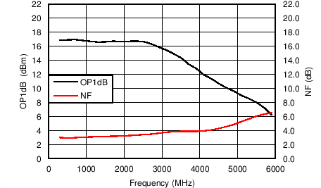 Figure 14. OP1dB and NF vs Frequency