ZHCSIY0 October 2018 TPS92515AHV-Q1
PRODUCTION DATA.
- 1 特性
- 2 应用
- 3 说明
- 4 修订历史记录
- 5 Device Comparison Table
- 6 Pin Configuration and Functions
- 7 Specifications
-
8 Detailed Description
- 8.1 Overview
- 8.2 Functional Block Diagram
- 8.3
Feature Description
- 8.3.1 General Operation
- 8.3.2 Current Sense Comparator
- 8.3.3 OFF Timer
- 8.3.4 OFF-Timer, Shunt FET Dimming or Shunted Output Condition
- 8.3.5 Internal N-channel MOSFET
- 8.3.6 VCC Internal Regulator and Undervoltage Lockout (UVLO)
- 8.3.7 Analog Adjust Input
- 8.3.8 Thermal Protection
- 8.3.9 Junction Temperature Relative Estimation
- 8.3.10 BOOT and BOOT UVLO
- 8.3.11 PWM (UVLO and Enable)
- 8.4 Device Functional Modes
-
9 Application and Implementation
- 9.1 Application Information
- 9.2
Typical Application
- 9.2.1 General Design Procedure
- 9.2.2 Design Requirements
- 9.2.3
Detailed Design Procedure
- 9.2.3.1 Calculating Duty Cycle
- 9.2.3.2 Calculate OFF-Time Estimate
- 9.2.3.3 Calculate OFF-Time Resistor ROFF
- 9.2.3.4 Calculate the Inductance Value
- 9.2.3.5 Calculate the Sense Resistance
- 9.2.3.6 Calculate Input Capacitance
- 9.2.3.7 Verify Peak Current for Inductor Selection
- 9.2.3.8 Calculate Output Capacitance
- 9.2.3.9 Calculate UVLO Resistance Values
- 9.2.4 Application Curves
- 9.3 Dos and Don'ts
- 10Power Supply Recommendations
- 11Layout
- 12器件和文档支持
- 13机械、封装和可订购信息
3 说明
TPS92515AHV-Q1 是一款包含低电阻 N 沟道 MOSFET 的紧凑型单片开关稳压器。此器件适用于高亮度 LED 照明 应用 ,满足效率、高带宽、PWM 或模拟调光和小尺寸方面的要求。
此稳压器具有恒定关断时间和峰值电流控制功能。工作原理十分简单:在基于输出电压的一段关断时间后,即开始导通时间。达到电感峰值电流阈值后,导通时间立即结束。TPS92515AHV-Q1 器件可配置为在分流 FET 调光周期的导通和关断时间内保持恒定的峰间纹波。此周期非常适合在整个分流 FET 调光范围内保持线性响应。
低失调电压的高侧比较器有助于实现稳态精度。可单独使用模拟或 PWM 调光技术或者同时使用这两种技术来调制 LED 电流。其他 特性 包括欠压闭锁 (UVLO)、宽输入电压操作、固有 LED 开路操作和热关断功能,其工作温度范围较宽。
TPS92515AHV-Q1 器件采用热增强型 10 引脚 HVSSOP 封装,提供高电压选件,输入电压范围高达 65V。
器件信息(1)
| 器件型号 | 封装 | 封装尺寸(标称值) |
|---|---|---|
| TPS92515AHV-Q1 | HVSSOP (10) | 3mm x 3mm |
- 要了解所有可用封装,请参见数据表末尾的可订购产品附录。
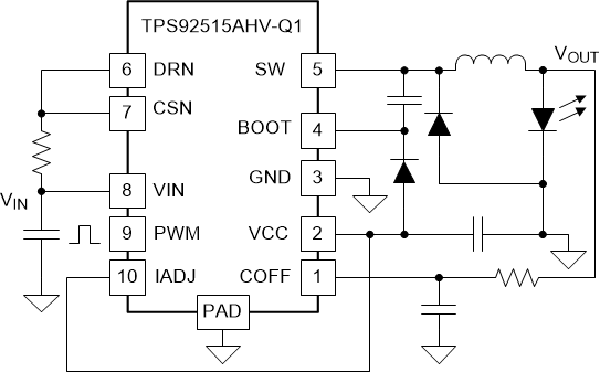
简化的降压 LED 驱动器应用
