ZHCSMP6A November 2020 – December 2021 TPS7H4010-SEP
PRODUCTION DATA
- 1 特性
- 2 应用
- 3 说明
- 4 Revision History
- 5 Pin Configuration and Functions
- 6 Specifications
-
7 Detailed Description
- 7.1 Overview
- 7.2 Functional Block Diagram
- 7.3
Feature Description
- 7.3.1 Synchronous Step-Down Regulator
- 7.3.2 Auto Mode and FPWM Mode
- 7.3.3 Fixed-Frequency Peak Current-Mode Control
- 7.3.4 Adjustable Output Voltage
- 7.3.5 Enable and UVLO
- 7.3.6 Internal LDO, VCC_UVLO, and BIAS Input
- 7.3.7 Soft Start and Voltage Tracking
- 7.3.8 Adjustable Switching Frequency
- 7.3.9 Frequency Synchronization and Mode Setting
- 7.3.10 Internal Compensation and CFF
- 7.3.11 Bootstrap Capacitor and VBOOT-UVLO
- 7.3.12 Power-Good and Overvoltage Protection
- 7.3.13 Overcurrent and Short-Circuit Protection
- 7.3.14 Thermal Shutdown
- 7.4 Device Functional Modes
-
8 Application and Implementation
- 8.1 Application Information
- 8.2
Typical Application
- 8.2.1 Design Requirements
- 8.2.2
Detailed Design Procedure
- 8.2.2.1 Output Voltage Setpoint
- 8.2.2.2 Switching Frequency
- 8.2.2.3 Input Capacitors
- 8.2.2.4 Inductor Selection
- 8.2.2.5 Output Capacitor Selection
- 8.2.2.6 Feed-Forward Capacitor
- 8.2.2.7 Bootstrap Capacitors
- 8.2.2.8 VCC Capacitor
- 8.2.2.9 BIAS
- 8.2.2.10 Soft Start
- 8.2.2.11 Undervoltage Lockout Setpoint
- 8.2.2.12 PGOOD
- 8.2.3 Application Curves
- 9 Power Supply Recommendations
- 10Layout
- 11Device and Documentation Support
- 12Mechanical, Packaging, and Orderable Information
封装选项
请参考 PDF 数据表获取器件具体的封装图。
机械数据 (封装 | 引脚)
- RNP|30
- KGD|0
散热焊盘机械数据 (封装 | 引脚)
- RNP|30
订购信息
1 特性
- 耐辐射
- SEL、SEB 和 SEGR 对于
LET 的抗扰度高达 43MeV-cm2/mg - SET 和 SEFI 的
LET 特征值高达 43MeV-cm2/mg - 每个晶圆批次的保障 TID 高达
20krad(Si) - TID 特征值高达 30krad(Si)
- SEL、SEB 和 SEGR 对于
- 增强型航天塑料
- 受控基线
- Au 键合线和 NiPdAu 铅涂层
- 采用增强型模塑化合物实现低释气
- 制造、组装和测试一体化基地
- 延长了产品生命周期
- 延长了产品变更通知
- 产品可追溯性
- 宽电压转换范围:
- tON-MIN = 60ns(典型值)
- tOFF-MIN = 70ns(典型值)
- 低 MOSFET 导通电阻:
- RDS_ON_HS = 53mΩ(典型值)
- RDS_ON_LS = 31mΩ(典型值)
- 可调频率范围:350 kHz 至 2.2MHz
- 可与外部时钟同步
- 内部补偿
- 电源正常状态标志
- 通过精密使能功能对系统 UVLO 进行编程
- 固定或可调的软启动时间
- 逐周期电流限制
- 具有断续模式的短路保护
- 热关断保护
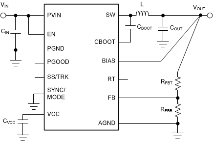
 简化版原理图