SLVS208J May 1999 – August 2015 TPS767
PRODUCTION DATA.
- 1 Features
- 2 Description
- 3 Revision History
- 4 Description (Continued)
- 5 Device Options
- 6 Pin Configuration and Functions
- 7 Specifications
- 8 Parameter Measurement Information
- 9 Detailed Description
- 10Application and Implementation
- 11Layout
- 12Device and Documentation Support
- 13Mechanical, Packaging, and Orderable Information
封装选项
请参考 PDF 数据表获取器件具体的封装图。
机械数据 (封装 | 引脚)
- D|8
- PWP|20
散热焊盘机械数据 (封装 | 引脚)
- PWP|20
订购信息
10 Application and Implementation
NOTE
Information in the following applications sections is not part of the TI component specification, and TI does not warrant its accuracy or completeness. TI’s customers are responsible for determining suitability of components for their purposes. Customers should validate and test their design implementation to confirm system functionality.
10.1 Application Information
The TPS767xx family includes eight fixed-output voltage regulators (1.5 V, 1.8 V, 2.5 V, 2.7 V, 2.8 V, 3.0 V, 3.3 V, and 5.0 V), and an adjustable regulator, the TPS76701 (adjustable from 1.5 V to 5.5 V).
10.1.1 External Capacitor Requirements
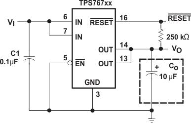
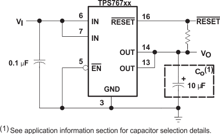
An input capacitor is not usually required; however, a ceramic bypass capacitor (0.047 µF or larger) improves load transient response and noise rejection if the TPS767xx is located more than a few inches from the power supply. A higher-capacitance electrolytic capacitor may be necessary if large (hundreds of milliamps) load transients with fast rise times are anticipated.
Like all low dropout regulators, the TPS767xx requires an output capacitor connected between OUT and GND to stabilize the internal control loop. The minimum recommended capacitance value is 10 µF and the ESR (equivalent series resistance) must be between 50 mΩ and 1.5 Ω. Capacitor values 10 µF or larger are acceptable, provided the ESR is less than 1.5 Ω. Solid tantalum electrolytic, aluminum electrolytic, and multilayer ceramic capacitors are all suitable, provided they meet the requirements described above. Most of the commercially available 10 µF surface-mount ceramic capacitors, including devices from Sprague and Kemet, meet the ESR requirements stated above.
10.2 Typical Application
 Figure 29. Typical Application Circuit (Fixed Versions)
 Figure 30. Typical Application Configuration (For Fixed Output Options)