ZHCSBL3C June   2013  – May 2017 TPS65150-Q1

PRODUCTION DATA.  

  1. 特性
  2. 应用
  3. 说明
  4. 修订历史记录
  5. Pin Configuration and Functions
  6. Specifications
    1. 6.1 Absolute Maximum Ratings
    2. 6.2 ESD Ratings
    3. 6.3 Recommended Operating Conditions
    4. 6.4 Thermal Information
    5. 6.5 Electrical Characteristics
    6. 6.6 Switching Characteristics
    7. 6.7 Typical Characteristics
  7. Detailed Description
    1. 7.1 Overview
    2. 7.2 Functional Block Diagram
    3. 7.3 Feature Description
      1. 7.3.1 Boost Converter
        1. 7.3.1.1 Setting the Boost Converter Output Voltage
        2. 7.3.1.2 Boost Converter Rectifier Diode
        3. 7.3.1.3 Choosing the Boost Converter Output Capacitance
        4. 7.3.1.4 Compensation
        5. 7.3.1.5 Soft Start
        6. 7.3.1.6 Gate Drive Signal
      2. 7.3.2 Negative Charge Pump
        1. 7.3.2.1 Negative Charge Pump Output Voltage
        2. 7.3.2.2 Negative Charge Pump Flying Capacitance
        3. 7.3.2.3 Negative Charge Pump Output Capacitance
        4. 7.3.2.4 Negative Charge Pump Diodes
      3. 7.3.3 Positive Charge Pump
        1. 7.3.3.1 Positive Charge Pump Output Voltage
        2. 7.3.3.2 Positive Charge Pump Flying Capacitance
        3. 7.3.3.3 Positive Charge Pump Output Capacitance
        4. 7.3.3.4 Positive Charge Pump Diodes
      4. 7.3.4 Power-On Sequencing, DLY1, DLY2
      5. 7.3.5 Gate Voltage Shaping
      6. 7.3.6 VCOM Buffer
      7. 7.3.7 Protection
        1. 7.3.7.1 Boost Converter Overvoltage Protection
        2. 7.3.7.2 Adjustable Fault Delay
        3. 7.3.7.3 Thermal Shutdown
        4. 7.3.7.4 Undervoltage Lockout
    4. 7.4 Device Functional Modes
      1. 7.4.1 VI > VIT+
      2. 7.4.2 VI < VIT-
      3. 7.4.3 Fault Mode
  8. Application and Implementation
    1. 8.1 Application Information
    2. 8.2 Typical Application
      1. 8.2.1 Design Requirements
      2. 8.2.2 Detailed Design Procedure
        1. 8.2.2.1  Boost Converter Design Procedure
          1. 8.2.2.1.1 Inductor Selection
        2. 8.2.2.2  Rectifier Diode Selection
        3. 8.2.2.3  Setting the Output Voltage
        4. 8.2.2.4  Output Capacitor Selection
        5. 8.2.2.5  Input Capacitor Selection
        6. 8.2.2.6  Compensation
        7. 8.2.2.7  Negative Charge Pump
          1. 8.2.2.7.1 Choosing the Output Capacitance
          2. 8.2.2.7.2 Choosing the Flying Capacitance
          3. 8.2.2.7.3 Choosing the Feedback Resistors
          4. 8.2.2.7.4 Choosing the Diodes
        8. 8.2.2.8  Positive Charge Pump
          1. 8.2.2.8.1 Choosing the Flying Capacitance
          2. 8.2.2.8.2 Choosing the Output Capacitance
          3. 8.2.2.8.3 Choosing the Feedback Resistors
          4. 8.2.2.8.4 Choosing the Diodes
        9. 8.2.2.9  Gate Voltage Shaping
        10. 8.2.2.10 Power-On Sequencing
        11. 8.2.2.11 Fault Delay
      3. 8.2.3 Application Curves
    3. 8.3 System Examples
  9. Power Supply Recommendations
  10. 10Layout
    1. 10.1 Layout Guidelines
    2. 10.2 Layout Example
  11. 11器件和文档支持
    1. 11.1 器件支持
      1. 11.1.1 Third-Party Products Disclaimer
    2. 11.2 接收文档更新通知
    3. 11.3 社区资源
    4. 11.4 商标
    5. 11.5 静电放电警告
    6. 11.6 Glossary
  12. 12机械、封装和可订购信息

封装选项

机械数据 (封装 | 引脚)
散热焊盘机械数据 (封装 | 引脚)
订购信息

特性

  • 符合 AEC-Q100 标准:的顶部
    • 器件温度 1 级:–40°C 至 125°C 结温范围
    • 器件人体放电模型 (HBM) 静电防护 (ESD) 分类符合 AEC - Q100-002
    • 器件带电器件模型 (CDM) ESD 分类符合 AEC-Q100-011
  • 输入电压范围:1.8V 至 6V
  • V(VS) 升压转换器
    • 输出电压高达 15V
    • 输出电压精度 < 1%
    • 2A 开关电流限值
  • V(VGH) 正向稳压电荷泵驱动器
    • 输出电压高达 30 V
    • 栅极电压整形
  • V(VGL) 负向稳压电荷泵驱动器
    • 输出电压低至 -15V
  • 集成 VCOM 缓冲器
  • 可调上电序列
    • 外部隔离 MOSFET 的栅极驱动信号,针对 V(VS)
  • DRV8303 中的 特性
    • 超出稳压范围保护
    • 过压保护
    • 可调故障检测时序
    • 热关断
  • 带有外露散热焊盘的 24 引脚 TSSOP 封装

应用

  • 4" 至 17"液晶 (LCD) 显示屏
    • 汽车信息娱乐系统和仪表板
    • 汽车导航系统
    • 后座娱乐系统
    • 智能车镜

说明

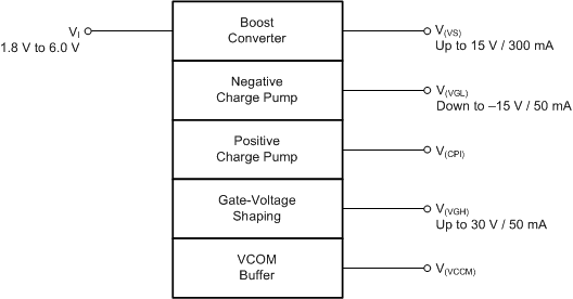
TPS65150-Q1 是一款电源,适用于汽车 LCD 应用。该器件集成了一个针对源极电压的升压转换器以及两个针对栅极电压并经过稳压的可调节电荷泵驱动器。为了削减外部成本、改善图像质量并减少影像残留,该器件采用 VCOM 缓冲器并具备栅极电压整形功能。

该器件经设计可由 1.8V 至 6V 的电源供电运行,非常适合 使用 3.3V 或 5V 固定输入电压轨的 汽车 LCD 应用。

VGL 和 VGH 的可调上电序列允许该器件针对各种显示屏进行优化。

为了防止系统发生故障,TPS65150-Q1 集成了可调节关断锁存功能。该器件监测输出(V(VS)、V(VGL) 和 V(VGH))。当其中一个输出低于其电源正常阈值的时间超过可调节故障延迟时间后,该器件进入关断模式。

器件信息(1)

器件型号 封装 封装尺寸(标称值)
TPS65150-Q1 TSSOP (24) 6.40mm x 7.80mm
  1. 如需了解所有可用封装,请参阅数据表末尾的可订购产品附录。

框图

TPS65150-Q1 FP_Block_SLVSBX4.gif