ZHCSFB9B June   2016  – March 2019 TPS63070

PRODUCTION DATA.  

  1. 特性
  2. 应用
  3. 说明
    1.     Device Images
      1.      简化原理图
      2.      效率与输出电流间的关系;Vo = 5V
  4. 修订历史记录
  5. Device Comparison Table
  6. Pin Configuration and Functions
    1.     Pin Functions
  7. Specifications
    1. 7.1 Absolute Maximum Ratings
    2. 7.2 ESD Ratings
    3. 7.3 Recommended Operating Conditions
    4. 7.4 Thermal Information
    5. 7.5 Electrical Characteristics
    6. 7.6 Typical Characteristics
  8. Detailed Description
    1. 8.1 Overview
    2. 8.2 Functional Block Diagram TPS63070
    3. 8.3 Functional Block Diagram TPS630701
    4. 8.4 Feature Description
      1. 8.4.1  Control Loop Description
      2. 8.4.2  Precise Enable
      3. 8.4.3  Power Good
      4. 8.4.4  Soft Start
      5. 8.4.5  PS/SYNC
      6. 8.4.6  Short Circuit Protection
      7. 8.4.7  VSEL and FB2 pins
      8. 8.4.8  Overvoltage Protection
      9. 8.4.9  Undervoltage Lockout
      10. 8.4.10 Overtemperature Protection
    5. 8.5 Device Functional Modes
      1. 8.5.1 Power Save Mode
      2. 8.5.2 Current Limit
      3. 8.5.3 Output Discharge Function (TPS630702 only)
  9. Application and Implementation
    1. 9.1 Application Information
    2. 9.2 Typical Application for adjustable version
      1. 9.2.1 Design Requirements
      2. 9.2.2 Detailed Design Procedure
        1. 9.2.2.1 Programming The Output Voltage
        2. 9.2.2.2 Inductor Selection
        3. 9.2.2.3 Capacitor Selection
          1. 9.2.2.3.1 Input Capacitor
          2. 9.2.2.3.2 Output Capacitor
      3. 9.2.3 Application Curves
    3. 9.3 Typical Application for Fixed Voltage Version
      1. 9.3.1 Design Requirements
      2. 9.3.2 Detailed Design Procedure
      3. 9.3.3 Application Curves
  10. 10Power Supply Recommendations
    1. 10.1 Thermal Information
  11. 11Layout
    1. 11.1 Layout Guidelines
    2. 11.2 Layout Example
  12. 12器件和文档支持
    1. 12.1 器件支持
      1. 12.1.1 第三方产品免责声明
    2. 12.2 相关链接
    3. 12.3 接收文档更新通知
    4. 12.4 社区资源
    5. 12.5 商标
    6. 12.6 静电放电警告
    7. 12.7 术语表
  13. 13机械、封装和可订购信息

封装选项

机械数据 (封装 | 引脚)
散热焊盘机械数据 (封装 | 引脚)
订购信息

VSEL and FB2 pins

The VSEL pin allows to dynamically select between two different output voltages on the adjustable version. The voltage is set by a resistor that is connected between the FB and the FB2 pin. FB2 is connected to GND if VSEL = high. FB2 is high impedance if VSEL= low. The transition speed during a voltage change is defined by the loop bandwidth of the device and can be adjusted by adding a feed-forward capacitor in parallel to R1.
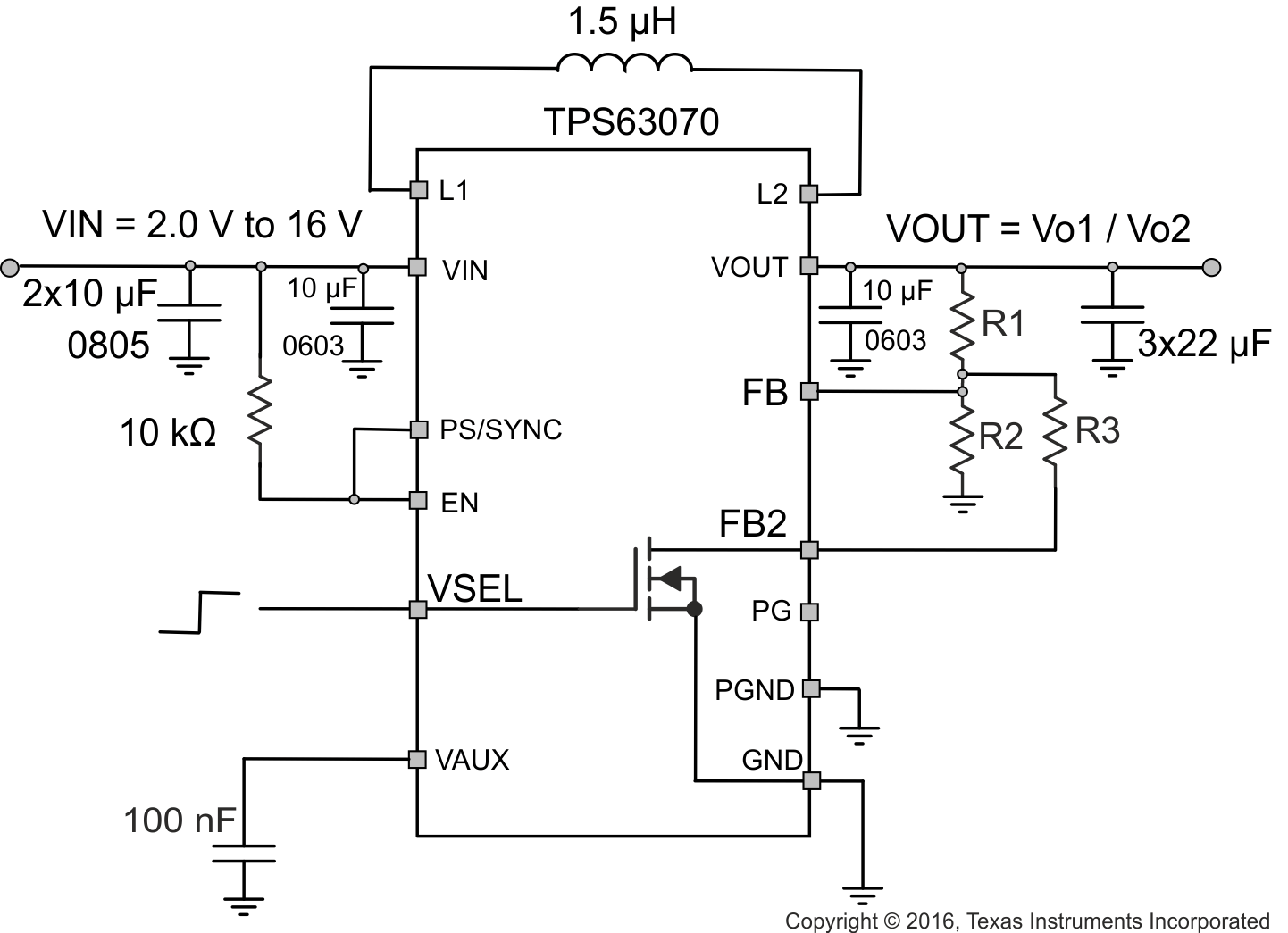
TPS63070 TPS63070_VSELonly_noILIM_SS.gifFigure 8. Typical Application using VSEL

The resistor values for the feedback divider and FB2 are in the 50-500kΩ range. R3 is calculated as follows:

Equation 1. TPS63070 Equation_new.gif

For more details on how to use VSEL see Technote SLVAE62.