ZHCSDR8 May 2015 TPS544B25 , TPS544C25
PRODUCTION DATA.
- 1 特性
- 2 应用范围
- 3 说明
- 4 修订历史记录
- 5 Device Comparison Table
- 6 Pin Configuration and Functions
- 7 Specifications
-
8 Detailed Description
- 8.1 Overview
- 8.2 Functional Block Diagram
- 8.3
Feature Description
- 8.3.1 Linear Regulators BP3 and BP6
- 8.3.2 Input Undervoltage Lockout (UVLO)
- 8.3.3 Turn-On and Turn-Off Delay and Sequencing
- 8.3.4 Voltage Reference
- 8.3.5 Differential Remote Sense
- 8.3.6 Set Output Voltage and Adapative Voltage Scaling (AVS)
- 8.3.7 Reset VOUT
- 8.3.8 Switching Frequency and Synchronization
- 8.3.9 Soft-Start and TON_RISE Command
- 8.3.10 Pre-Biased Output Start-Up
- 8.3.11 Soft-Stop and TOFF_FALL Command
- 8.3.12 Current Monitoring and Low-Side MOSFET Overcurrent Protection
- 8.3.13 High-Side MOSFET Short-Circuit Protection
- 8.3.14 Over-Temperature Protection
- 8.3.15 Output Overvoltage and Undervoltage Protection
- 8.3.16 TON_MAX Fault
- 8.3.17 Power Good (PGOOD) Indicator
- 8.3.18 Fault Protection Responses
- 8.3.19 Switching Node
- 8.3.20 PMBus General Description
- 8.3.21 PMBus Address
- 8.3.22 PMBus Connections
- 8.3.23 Auto ARA (Alert Response Address) Response
- 8.4 Device Functional Modes
- 8.5 Supported PMBus Commands
- 8.6
Register Maps
- 8.6.1 OPERATION (01h)
- 8.6.2 ON_OFF_CONFIG (02h)
- 8.6.3 CLEAR_FAULTS (03h)
- 8.6.4 WRITE_PROTECT (10h)
- 8.6.5 STORE_DEFAULT_ALL (11h)
- 8.6.6 RESTORE_DEFAULT_ALL (12h)
- 8.6.7 CAPABILITY (19h)
- 8.6.8 SMBALERT_MASK (1Bh)
- 8.6.9 VOUT_MODE (20h)
- 8.6.10 VOUT_COMMAND (21h)
- 8.6.11 VOUT_MAX (24h)
- 8.6.12 VOUT_TRANSITION_RATE (27h)
- 8.6.13 VOUT_SCALE_LOOP (29h)
- 8.6.14 VIN_ON (35h)
- 8.6.15 VIN_OFF (36h)
- 8.6.16 IOUT_CAL_OFFSET (39h)
- 8.6.17 VOUT_OV_FAULT_LIMIT (40h)
- 8.6.18 VOUT_OV_FAULT_RESPONSE (41h)
- 8.6.19 VOUT_OV_WARN_LIMIT (42h)
- 8.6.20 VOUT_UV_WARN_LIMIT (43h)
- 8.6.21 VOUT_UV_FAULT_LIMIT (44h)
- 8.6.22 VOUT_UV_FAULT_RESPONSE (45h)
- 8.6.23 IOUT_OC_FAULT_LIMIT (46h)
- 8.6.24 IOUT_OC_FAULT_RESPONSE (47h)
- 8.6.25 IOUT_OC_WARN_LIMIT (4Ah)
- 8.6.26 OT_FAULT_LIMIT (4Fh)
- 8.6.27 OT_FAULT_RESPONSE (50h)
- 8.6.28 OT_WARN_LIMIT (51h)
- 8.6.29 TON_DELAY (60h)
- 8.6.30 TON_RISE (61h)
- 8.6.31 TON_MAX_FAULT_LIMIT (62h)
- 8.6.32 TON_MAX_FAULT_RESPONSE (63h)
- 8.6.33 TOFF_DELAY (64h)
- 8.6.34 TOFF_FALL (65h)
- 8.6.35 STATUS_BYTE (78h)
- 8.6.36 STATUS_WORD (79h)
- 8.6.37 STATUS_VOUT (7Ah)
- 8.6.38 STATUS_IOUT (7Bh)
- 8.6.39 STATUS_INPUT (7Ch)
- 8.6.40 STATUS_TEMPERATURE (7Dh)
- 8.6.41 STATUS_CML (7Eh)
- 8.6.42 STATUS_MFR_SPECIFIC (80h)
- 8.6.43 READ_VOUT (8Bh)
- 8.6.44 READ_IOUT (8Ch)
- 8.6.45 READ_TEMPERATURE_2 (8Eh)
- 8.6.46 PMBUS_REVISION (98h)
- 8.6.47 MFR_VOUT_MIN (A4h)
- 8.6.48 IC_DEVICE_ID (ADh)
- 8.6.49 IC_DEVICE_REV (AEh)
- 8.6.50 MFR_SPECIFIC_00 (D0h)
- 8.6.51 OPTIONS (MFR_SPECIFIC_21) (E5h)
- 8.6.52 MISC_CONFIG_OPTIONS (MFR_SPECIFIC_32) (F0h)
-
9 Applications and Implementation
- 9.1 Application Information
- 9.2
Typical Applications
- 9.2.1 TPS544C25 4.5-V to 18-V Input, 0.95-V Output, 30-A Converter
- 9.2.2 Design Requirements
- 9.2.3
Design Procedure
- 9.2.3.1 Switching Frequency Selection
- 9.2.3.2 Inductor Selection
- 9.2.3.3 Output Capacitor Selection
- 9.2.3.4 Input Capacitor Selection
- 9.2.3.5 Bootstrap Capacitor Selection
- 9.2.3.6 BP6 and BP3
- 9.2.3.7 R-C Snubber and VIN Pin High-Frequency Bypass
- 9.2.3.8 Temperature Sensor
- 9.2.3.9 Key PMBus Parameter Selection
- 9.2.3.10 Output Voltage Setting and Frequency Compensation Selection
- 9.2.4 Application Curves
- 10Power Supply Recommendations
- 11Layout
- 12器件和文档支持
- 13机械、封装和可订购信息
12 器件和文档支持
12.1 器件支持
12.1.1 开发支持
12.1.1.1 德州仪器 (TI) Fusion Digital Power Designer
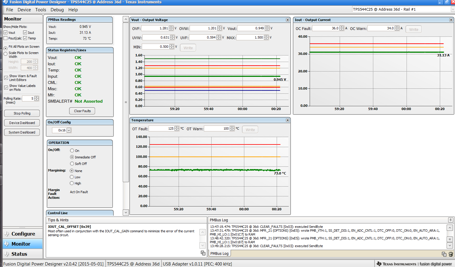
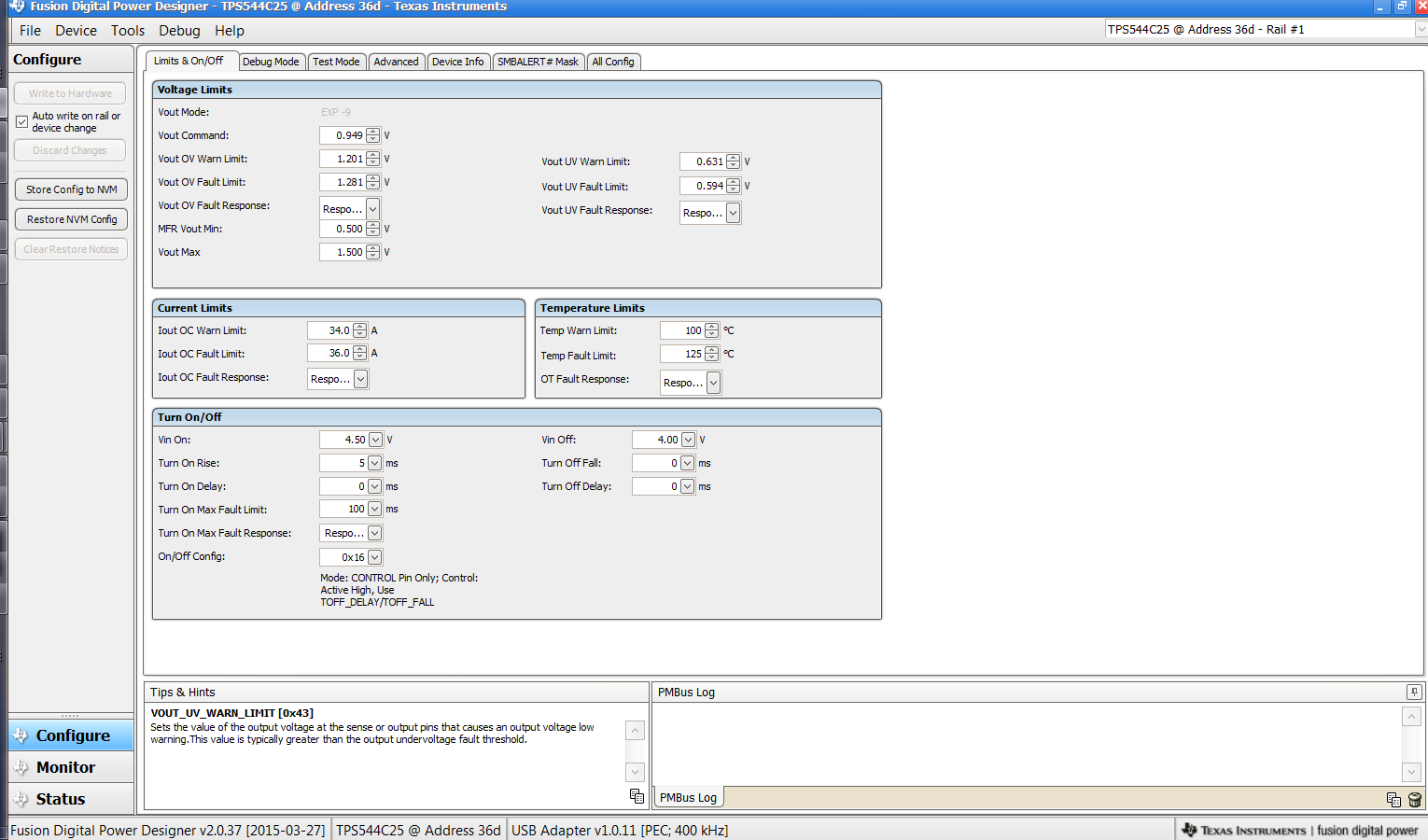
德州仪器 (TI) Digital Power Designer 能够为 TPS544x25器件提供全面支持。Fusion digital Power Designer 是一款图形用户界面 (GUI),可使用德州仪器 (TI) USB-to-GPIO 适配器通过 PMBus 配置并监控器件。
单击此链接下载德州仪器 (TI) Fusion Digital Power Designer 软件包。
 Figure 57. 使用 Fusion Digital Power Designer 进行器件监控
 Figure 58. 使用 Fusion Digital Power Designer 进行器件配置
12.1.1.2 TPS40k 环路补偿工具
TPS544x25 器件受德州仪器 (TI) TPS40k 环路补偿工具 支持。该电子表格工具可用于计算具有电压模式控制功能的器件的频率补偿组件。
12.2 相关链接
下面的表格列出了快速访问链接。类别包括技术文档、支持与社区资源、工具和软件,以及申请样片或购买产品的快速链接。
12.3 社区资源
下列链接提供到 TI 社区资源的连接。链接的内容由各个分销商“按照原样”提供。这些内容并不构成 TI 技术规范,并且不一定反映 TI 的观点;请参阅 TI 的 《使用条款》。
-
TI E2E™ 在线社区 TI 的工程师对工程师 (E2E) 社区。此社区的创建目的在于促进工程师之间的协作。在 e2e.ti.com 中,您可以咨询问题、分享知识、拓展思路并与同行工程师一道帮助解决问题。
-
设计支持 TI 参考设计支持 可帮助您快速查找有帮助的 E2E 论坛、设计支持工具以及技术支持的联系信息。
12.4 商标
E2E is a trademark of Texas Instruments.
PMBus is a trademark of SMIF, Inc..
NexFET is a trademark of TI.
All other trademarks are the property of their respective owners.
12.5 静电放电警告

这些装置包含有限的内置 ESD 保护。 存储或装卸时,应将导线一起截短或将装置放置于导电泡棉中,以防止 MOS 门极遭受静电损伤。
12.6 Glossary
SLYZ022 — TI Glossary.
This glossary lists and explains terms, acronyms, and definitions.