ZHCSCI5B May 2014 – July 2016 TPS544B20 , TPS544C20
PRODUCTION DATA.
- 1 特性
- 2 应用范围
- 3 说明
- 4 修订历史记录
- 5 Device Comparison Table
- 6 Pin Configuration and Functions
- 7 Specifications
-
8 Detailed Description
- 8.1 Overview
- 8.2 Functional Block Diagram
- 8.3
Feature Description
- 8.3.1 Turn-On and Turn-Off Delay and Sequencing
- 8.3.2 Pre-Biased Output Start-Up
- 8.3.3 Voltage Reference
- 8.3.4 Differential Remote Sense and Output Voltage Setting
- 8.3.5 PMBus Output Voltage Adjustment
- 8.3.6 Switching Frequency
- 8.3.7 Soft-Start
- 8.3.8 Linear Regulators BP3 and BP6
- 8.3.9 External Bypass (BPEXT)
- 8.3.10 Current Monitoring and Low-Side MOSFET Overcurrent Protection
- 8.3.11 High-Side MOSFET Short-Circuit Protection
- 8.3.12 Over-Temperature Protection
- 8.3.13 Input Undervoltage Lockout (UVLO)
- 8.3.14 Output Overvoltage and Undervoltage Protection
- 8.3.15 Fault Protection Responses
- 8.3.16 PMBus General Description
- 8.3.17 PMBus Address
- 8.3.18 PMBus Connections
- 8.3.19 Auto ARA (Alert Response Address) Response
- 8.4 Device Functional Modes
- 8.5 Programming
- 8.6
Register Maps
- 8.6.1 OPERATION (01h)
- 8.6.2 ON_OFF_CONFIG (02h)
- 8.6.3 CLEAR_FAULTS (03h)
- 8.6.4 WRITE_PROTECT (10h)
- 8.6.5 STORE_USER_ALL (15h)
- 8.6.6 RESTORE_USER_ALL (16h)
- 8.6.7 CAPABILITY (19h)
- 8.6.8 VOUT_MODE (20h)
- 8.6.9 VIN_ON (35h)
- 8.6.10 VIN_OFF (36h)
- 8.6.11 IOUT_CAL_OFFSET (39h)
- 8.6.12 IOUT_OC_FAULT_LIMIT (46h)
- 8.6.13 IOUT_OC_FAULT_RESPONSE (47h)
- 8.6.14 IOUT_OC_WARN_LIMIT (4Ah)
- 8.6.15 OT_FAULT_LIMIT (4Fh)
- 8.6.16 OT_WARN_LIMIT (51h)
- 8.6.17 TON_RISE (61h)
- 8.6.18 STATUS_BYTE (78h)
- 8.6.19 STATUS_WORD (79h)
- 8.6.20 STATUS_VOUT (7Ah)
- 8.6.21 STATUS_IOUT (7Bh)
- 8.6.22 STATUS_TEMPERATURE (7Dh)
- 8.6.23 STATUS_CML (7Eh)
- 8.6.24 STATUS_MFR_SPECIFIC (80h)
- 8.6.25 READ_VOUT (8Bh)
- 8.6.26 READ_IOUT (8Ch)
- 8.6.27 READ_TEMPERATURE_2 (8Eh)
- 8.6.28 PMBUS_REVISION (98h)
- 8.6.29 MFR_SPECIFIC_00 (D0h)
- 8.6.30 VREF_TRIM (MFR_SPECIFIC_04) (D4h)
- 8.6.31 STEP_VREF_MARGIN_HIGH (MFR_SPECIFIC_05) (D5h)
- 8.6.32 STEP_VREF_MARGIN_LOW (MFR_SPECIFIC_06) (D6h)
- 8.6.33 PCT_VOUT_FAULT_PG_LIMIT (MFR_SPECIFIC_07) (D7h)
- 8.6.34 SEQUENCE_TON_TOFF_DELAY (MFR_SPECIFIC_08) (D8h)
- 8.6.35 OPTIONS (MFR_SPECIFIC_21) (E5h)
- 8.6.36 MASK_SMBALERT (MFR_SPECIFIC_23) (E7h)
- 8.6.37 DEVICE_CODE (MFR_SPECIFIC_44) (FCh)
-
9 Applications and Implementation
- 9.1 Application Information
- 9.2
Typical Application
- 9.2.1 Design Requirements
- 9.2.2
Detailed Design Procedure
- 9.2.2.1 Switching Frequency Selection
- 9.2.2.2 Inductor Selection
- 9.2.2.3 Output Capacitor Selection
- 9.2.2.4 D-CAP Mode and D-CAP2 Mode Stability
- 9.2.2.5 Input Capacitor Selection
- 9.2.2.6 Bootstrap Capacitor and Resistor Selection
- 9.2.2.7 BP6, BP3 and BPEXT
- 9.2.2.8 R-C Snubber and VIN Pin High-Frequency Bypass
- 9.2.2.9 Temperature Sensor
- 9.2.2.10 Key PMBus Parameter Selection
- 9.2.2.11 Output Voltage Setting and Frequency Compensation Selection
- 9.2.3 Application Curves
- 10Power Supply Recommendations
- 11Layout
- 12器件和文档支持
- 13机械、封装和可订购信息
12 器件和文档支持
12.1 器件支持
12.1.1 开发支持
12.1.1.1 德州仪器 (TI) Fusion Digital Power™设计人员
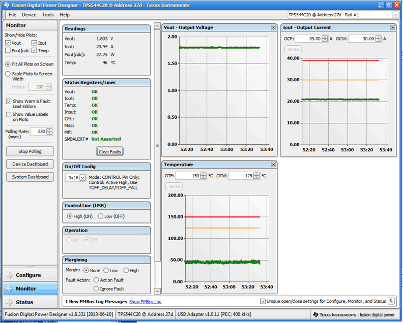
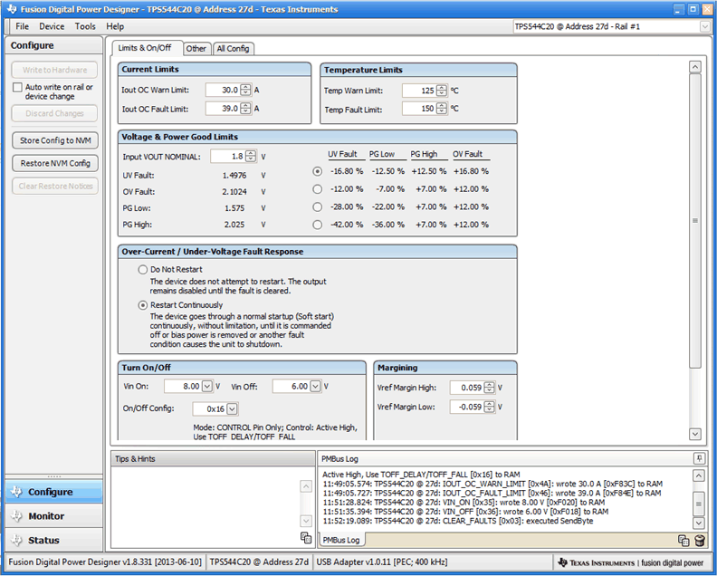
TPS544B20 和 TPS544C20 器件由德州仪器 (TI) 数字电源设计工具 (Digital Power Designer) 完全支持。Fusion Digital Power Designer 是一款图形用户界面 (GUI),此界面可根据 PMBus 接口协议,经由德州仪器 (TI) USB 到通用输入输出接口 (GPIO) 适配器来配置和监视 TPS544B20 和 TPS544C20 器件。
单击此链接下载德州仪器 (TI) Fusion Digital Power Designer 软件包。
 Figure 48. 使用 Fusion Digital Power Designer 进行器件监控
 Figure 49. 使用 Fusion Digital Power Designer 进行器件配置
12.2 相关链接
下面的表格列出了快速访问链接。类别包括技术文档、支持与社区资源、工具和软件,以及申请样片或购买产品的快速链接。
12.3 商标
E2E is a trademark of Texas Instruments.
NexFET, D-CAP, D-CAP2, Fusion Digital Power are trademarks of TI.
All other trademarks are the property of their respective owners.
12.4 接收文档更新通知
要接收文档更新通知,请导航至 TI.com 上的器件产品文件夹。单击右上角的通知我 进行注册,即可每周接收产品信息更改摘要。有关更改的详细信息,请查看任何已修订文档中包含的修订历史记录。
12.5 社区资源
下列链接提供到 TI 社区资源的连接。链接的内容由各个分销商“按照原样”提供。这些内容并不构成 TI 技术规范,并且不一定反映 TI 的观点;请参阅 TI 的 《使用条款》。
-
TI E2E™ 在线社区 TI 的工程师对工程师 (E2E) 社区。此社区的创建目的在于促进工程师之间的协作。在 e2e.ti.com 中,您可以咨询问题、分享知识、拓展思路并与同行工程师一道帮助解决问题。
-
设计支持 TI 参考设计支持 可帮助您快速查找有帮助的 E2E 论坛、设计支持工具以及技术支持的联系信息。
12.6 静电放电警告

这些装置包含有限的内置 ESD 保护。 存储或装卸时,应将导线一起截短或将装置放置于导电泡棉中,以防止 MOS 门极遭受静电损伤。
12.7 Glossary
SLYZ022 — TI Glossary.
This glossary lists and explains terms, acronyms, and definitions.