ZHCSCQ0 August 2014 TPS25921A , TPS25921L
PRODUCTION DATA.
- 1 特性
- 2 应用范围
- 3 说明
- 4 应用电路原理图
- 5 修订历史记录
- 6 Pin Configuration and Functions
- 7 Specifications
- 8 Parametric Measurement Information
-
9 Detailed Description
- 9.1 Overview
- 9.2 Functional Block Diagram
- 9.3 Feature Description
- 9.4 Device Functional Modes
-
10Applications and Implementation
- 10.1 Application Information
- 10.2
Typical Application
- 10.2.1
Precision Current Limiting and Protection for White Goods
- 10.2.1.1 Design Requirements
- 10.2.1.2 Detailed Design Procedure
- 10.2.1.3 Application Curves
- 10.2.1
Precision Current Limiting and Protection for White Goods
- 11System Examples
- 12Power Supply Recommendations
- 13Layout
- 14器件和文档支持
- 15机械封装和可订购信息
11 System Examples
The TPS25921 provides a simple solution for current limiting, inrush current control and supervision of power rails for wide range of applications operating at 4.5 V to 18 V and delivering up to 1.5 A.
11.1 Protection and Current Limiting for Primary-Side Regulated Power Supplies
Primary side regulated power supplies and adapters are dominant today in many of the applications such as Smart-phones, Portable hand-held devices, White Goods, Set-Top-Box and Gaming consoles. These supplies provide efficient, low cost and low component count solutions for power needs ranging from 5W to 30W. But, these come with drawbacks of
- No secondary side protection for immediate termination of critical faults such as short circuit and over voltage
- Do not provide precise current limiting for overload transients
- Have poor output voltage regulation for sudden change in AC input voltages - triggering output overvoltage condition
Many of the above applications require precise output current limiting and secondary side protection, driving the need for current sensing in the secondary side. This needs additional circuit implementation using precision operational amplifiers. This increases the complexity of the solution and also results in sensing losses The TPS25921 with its integrated low-ohmic N-channel FET provides a simple and efficient solution. Figure 47 shows the typical implementation using TPS25921.
 Figure 47. Current Limiting and Protection for AC-DC Power Supplies
During short circuit conditions, the internal fast comparator of TPS25921 turns OFF the internal FET in less than 3 µs (typical) as soon as current exceeds I(FASTRIP), set by the current limit R(ILIM) resistor. The OVP comparator with 3% precision helps in quick isolation of the load from the input when inputs exceeds the set V(OVPR)
Figure 42 and Figure 38 shows short circuit and overvoltage response waveforms of implementation using TPS25921. In addition to above, the TPS25921 provides inrush current limit when output is hot-plugged into any of the system loads.
11.2 Precision Current Limiting in Intrinsic Safety Applications
Intrinsic safety (IS) is becoming prominent need for safe operation of electrical and electronic equipment in hazardous areas. Intrinsic safety requires that equipment is designed such that the total amount of energy available in the apparatus is simply not enough to ignite an explosive atmosphere. The energy can be electrical, in the form of a spark, or thermal, in the form of a hot surface.
This calls for precise current limiting and precision shutdown of the circuit for over voltage conditions ensuring that set voltage and current limits are not exceeded for wide operating temperature range and variable environmental conditions. Applications such as Gas Analyzers, Medical equipment (such as electrocardiographs), Portal Industrial Equipment, Cabled Power distribution systems and hand-held motor operated tools need to meet these critical safety standards.
The TPS25921 device can be used as simple protection solution for each of the internal rails. Figure 48 shows the typical implementation using TPS25921.
 Figure 48. Precision current Limit and Protection of Internal Rails
11.3 Smart Load Switch
A smart load switch is a series FET used for switching of the load (resistive or inductive). It also provides protection during fault conditions. Typical discrete implementation is shown in Figure 49. Discrete solutions have higher component count and require complex circuitry to implement each of the protection fault needs.
TPS25921 can be used as a smart power switch for applications ranging from 4.5 V to 18 V. TPS25921 provides programmable soft start, programmable current limits, over-temperature protection, a fault flag, and under-voltage lockout.
 Figure 49. Smart Load Switch Implementation
Figure 49 shows typical implementation and usage as load switch. This configuration can be used for driving a solenoid and FAN control. It is recommended to use a freewheeling diode across the load when load is highly inductive.
Figure 50 shows load switching waveforms using TPS25921 for 12 V Bus
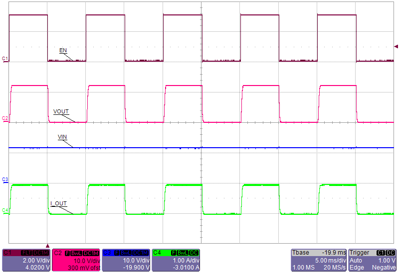 Figure 50. Smart Load Switch (100 Hz Operation)