SLVS038I January 1989 – July 2016 TL2842 , TL2843 , TL2844 , TL2845 , TL3842 , TL3843 , TL3844 , TL3845
PRODUCTION DATA.
- 1 Features
- 2 Applications
- 3 Description
- 4 Revision History
- 5 Pin Configuration and Functions
- 6 Specifications
- 7 Detailed Description
- 8 Application and Implementation
- 9 Power Supply Recommendations
- 10Layout
- 11Device and Documentation Support
- 12Mechanical, Packaging, and Orderable Information
封装选项
请参考 PDF 数据表获取器件具体的封装图。
机械数据 (封装 | 引脚)
- D|8
- D|14
- P|8
散热焊盘机械数据 (封装 | 引脚)
订购信息
8 Application and Implementation
NOTE
Information in the following applications sections is not part of the TI component specification, and TI does not warrant its accuracy or completeness. TI’s customers are responsible for determining suitability of components for their purposes. Customers should validate and test their design implementation to confirm system functionality.
8.1 Typical Application
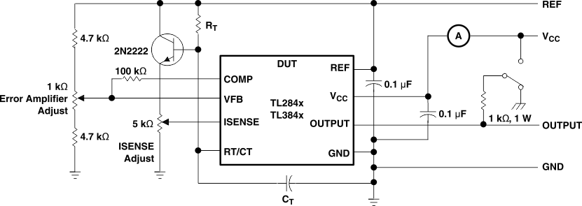
The following application is an open-loop laboratory test fixture. This circuit demonstrates the setup and use of the TL284x and TL384x devices and their internal circuitry.
In the open-loop laboratory test fixture (see Figure 13), high peak currents associated with loads necessitate careful grounding techniques. Timing and bypass capacitors should be connected close to the GND terminal in a single-point ground. The transistor and 5-kΩ potentiometer sample the oscillator waveform and apply an adjustable ramp to the ISENSE terminal.
 Figure 13. Open-Loop Laboratory Test Fixture
8.1.1 Design Requirements
The design techniques in the following sections may be used for power supply PWM applications which fall within the following requirements.
- 500-kHz or lower operation
- 30-V or less output voltage
- 200-mA or less output current
8.1.2 Detailed Design Procedure
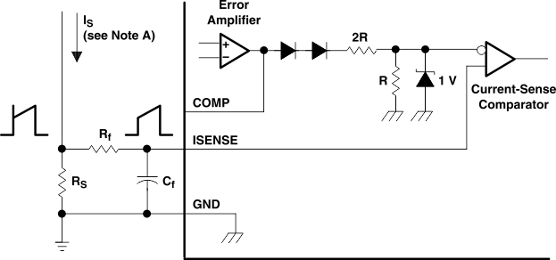
8.1.2.1 Current-Sense Circuit

 A small RC filter formed by resistor Rf and capacitor Cf may be required to suppress switch transients.
8.1.2.2 Error-Amplifier Configuration

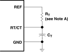
8.1.2.3 Oscillator Section


8.1.3 Application Curve
The application curve shows oscillator characteristics for chosen capacitor and resistor values.
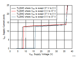
 Figure 17. Supply Current vs Supply Voltage