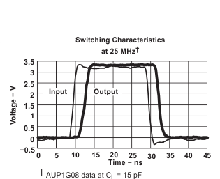
The AUP family is TI's premier solution to the industry's low-power needs in battery-powered portable applications. This family assures a very-low static and dynamic power consumption across the entire VCC range of 0.8 V to 3.6 V, thus resulting in an increased battery life. The AUP devices also maintain excellent signal integrity.
The SN74AUP1G79 is a single positive-edge-triggered D-type flip-flop. When data at the data (D) input meets the setup-time requirement, the data is transferred to the Q output on the positive-going edge of the clock pulse. Clock triggering occurs at a voltage level and is not directly related to the rise time of the clock pulse. Following the hold-time interval, data at the D input can be changed without affecting the levels at the outputs.
NanoStar™ package technology is a major breakthrough in IC packaging concepts, using the die as the package.
The SN74AUP1G79 device is fully specified for partial-power-down applications using Ioff. The Ioff circuitry disables the outputs when the device is powered down. This inhibits current backflow into the device which prevents damage to the device.
PART NUMBER | PACKAGE | BODY SIZE (NOM) |
---|---|---|
SN74AUP1G79DBV | SOT-23 (5) | 2.90 mm × 1.60 mm |
SN74AUP1G79DCK | SC70 (5) | 2.00 mm × 1.25 mm |
SN74AUP1G79DRL | SOT-5X3 (5) | 1.60 mm × 1.20 mm |
SN74AUP1G79DRY | SON (6) | 1.45 mm × 1.00 mm |
SN74AUP1G79DSF | SON (6) | 1.00 mm × 1.00 mm |
SN74AUP1G79DPW | X2SON (5) | 0.80 mm x 0.80 mm |
SN74AUP1G79YFP | DSBGA (6) | 1.16 mm × 0.76 mm |
SN74AUP1G79YZP | DSBGA (5) | 1.39 mm × 0.89 mm |
Changes from H Revision (April 2015) to I Revision
Changes from G Revision (May 2010) to H Revision
PIN | I/O | DESCRIPTION | ||||
---|---|---|---|---|---|---|
NAME | DBV, DCK, DRL, DPW |
DRY, DSF |
YZP | YFP | ||
CLK | 2 | 2 | B1 | B1 | I | Positive-Edge-Triggered Clock input |
D | 1 | 1 | A1 | A1 | I | Data Input |
GND | 3 | 3 | C1 | C1 | — | Ground pin |
NC | — | 5 | — | B2 | — | No Connect |
Q | 4 | 4 | C2 | C2 | O | Q output |
VCC | 5 | 6 | A2 | A2 | — | Positive supply |
MIN | MAX | UNIT | |||
---|---|---|---|---|---|
VCC | Supply voltage | –0.5 | 4.6 | V | |
VI | Input voltage(2) | –0.5 | 4.6 | V | |
VO | Voltage range applied to any output in the high-impedance or power-off state(2) | –0.5 | 4.6 | V | |
VO | Output voltage range in the high or low state(2) | –0.5 | VCC + 0.5 | V | |
IIK | Input clamp current | VI < 0 | –50 | mA | |
IOK | Output clamp current | VO < 0 | –50 | mA | |
IO | Continuous output current | ±20 | mA | ||
Continuous current through VCC or GND | ±50 | mA | |||
TJ | Maximum junction temperature | 150 | °C | ||
Tstg | Storage temperature | –65 | 150 | °C |
VALUE | UNIT | |||
---|---|---|---|---|
V(ESD) | Electrostatic discharge | Human-body model (HBM), per ANSI/ESDA/JEDEC JS-001(1) | 2000 | V |
Charged-device model (CDM), per JEDEC specification JESD22-C101(2) | 1000 |
MIN | MAX | UNIT | |||
---|---|---|---|---|---|
VCC | Supply voltage | 0.8 | 3.6 | V | |
VIH | High-level input voltage | VCC = 0.8 V | VCC | V | |
VCC = 1.1 V to 1.95 V | 0.65 × VCC | ||||
VCC = 2.3 V to 2.7 V | 1.6 | ||||
VCC = 3 V to 3.6 V | 2 | ||||
VIL | Low-level input voltage | VCC = 0.8 V | 0 | V | |
VCC = 1.1 V to 1.95 V | 0.35 × VCC | ||||
VCC = 2.3 V to 2.7 V | 0.7 | ||||
VCC = 3 V to 3.6 V | 0.9 | ||||
VI | Input voltage(1) | 0 | 3.6 | V | |
VO | Output voltage | 0 | VCC | V | |
IOH | High-level output current | VCC = 0.8 V | –20 | µA | |
VCC = 1.1 V | –1.1 | mA | |||
VCC = 1.4 V | –1.7 | ||||
VCC = 1.65 V | –1.9 | ||||
VCC = 2.3 V | –3.1 | ||||
VCC = 3 V | –4 | ||||
IOL | Low-level output current | VCC = 0.8 V | 20 | µA | |
VCC = 1.1 V | 1.1 | mA | |||
VCC = 1.4 V | 1.7 | ||||
VCC = 1.65 V | 1.9 | ||||
VCC = 2.3 V | 3.1 | ||||
VCC = 3 V | 4 | ||||
Δt/Δv | Input transition rise or fall rate | VCC = 0.8 V to 3.6 V | 200 | ns/V | |
TA | Operating free-air temperature | –40 | 85 | °C |
THERMAL METRIC(1) | SN74AUP1G79 | UNIT | ||||||||
---|---|---|---|---|---|---|---|---|---|---|
DBV (SOT-23) |
DCK (SC70) |
DRL (SOT-5X3) |
DRY (SON) |
DSF (SON) |
DPW (X2SON) |
YFP (DSBGA) |
YZP (DSBGA) |
|||
5 PINS | 5 PINS | 5 PINS | 6 PINS | 6 PINS | 5 PINS | 6 PINS | 5 PINS | |||
RθJA | Junction-to-ambient thermal resistance | 267.2 | 284.1 | 294.1 | 341.1 | 377.1 | 489.2 | 125.4 | 146.2 | °C/W |
RθJC(top) | Junction-to-case (top) thermal resistance | 191.9 | 208.5 | 132.5 | 233.1 | 187.7 | 226.3 | 1.9 | 1.4 | °C/W |
RθJB | Junction-to-board thermal resistance | 101.1 | 103.1 | 143.4 | 206.7 | 236.6 | 352.9 | 37.2 | 39.3 | °C/W |
ψJT | Junction-to-top characterization parameter | 83.0 | 76.6 | 14.5 | 63.4 | 29.0 | 38.2 | 0.5 | 0.7 | °C/W |
ψJB | Junction-to-board characterization parameter | 100.8 | 102.3 | 143.9 | 206.7 | 236.3 | 352.1 | 37.5 | 39.8 | °C/W |
RθJC(bot) | Junction-to-case (bottom) thermal resistance | N/A | N/A | N/A | N/A | N/A | 150.8 | N/A | N/A | °C/W |
PARAMETER | TEST CONDITIONS | VCC | MIN | TYP | MAX | UNIT | ||
---|---|---|---|---|---|---|---|---|
VOH | IOH = –20 µA | 0.8 V to 3.6 V | VCC – 0.1 | V | ||||
IOH = –1.1 mA | 1.1 V | 0.75 × VCC | ||||||
IOH = –1.7 mA | 1.4 V | 1.11 | ||||||
IOH = –1.9 mA | 1.65 V | 1.32 | ||||||
IOH = –2.3 mA | 2.3 V | 2.05 | ||||||
IOH = –3.1 mA | 1.9 | |||||||
IOH = –2.7 mA | 3 V | 2.72 | ||||||
IOH = –4 mA | 2.6 | |||||||
VOL | IOL = 20 µA | 0.8 V to 3.6 V | 0.1 | V | ||||
IOL = 1.1 mA | 1.1 V | 0.3 × VCC | ||||||
IOL = 1.7 mA | 1.4 V | 0.31 | ||||||
IOL = 1.9 mA | 1.65 V | 0.31 | ||||||
IOL = 2.3 mA | 2.3 V | 0.31 | ||||||
IOL = 3.1 mA | 0.44 | |||||||
IOL = 2.7 mA | 3 V | 0.31 | ||||||
IOL = 4 mA | 0.44 | |||||||
II | D or CLK input |
VI = GND to 3.6 V | 0 V to 3.6 V | 0.1 | µA | |||
Ioff | VI or VO = 0 V to 3.6 V | 0 V | 0.2 | µA | ||||
ΔIoff | VI or VO = 0 V to 3.6 V | 0 V to 0.2 V | 0.2 | µA | ||||
ICC | VI = GND or VCC to 3.6 V, | IO = 0 | 0.8 V to 3.6 V | 0.5 | µA | |||
ΔICC | VI = VCC – 0.6 V,(1) | IO = 0 | 3.3 V | 40 | µA | |||
Ci | VI = VCC or GND | 0 V | 1.5 | pF | ||||
3.6 V | 1.5 | |||||||
Co | VO = GND | 0 V | 3 | pF |
PARAMETER | TEST CONDITIONS | VCC | MIN | MAX | UNIT | ||
---|---|---|---|---|---|---|---|
VOH | IOH = –20 µA | 0.8 V to 3.6 V | VCC – 0.1 | V | |||
IOH = –1.1 mA | 1.1 V | 0.7 × VCC | |||||
IOH = –1.7 mA | 1.4 V | 1.03 | |||||
IOH = –1.9 mA | 1.65 V | 1.3 | |||||
IOH = –2.3 mA | 2.3 V | 1.97 | |||||
IOH = –3.1 mA | 1.85 | ||||||
IOH = –2.7 mA | 3 V | 2.67 | |||||
IOH = –4 mA | 2.55 | ||||||
VOL | IOL = 20 µA | 0.8 V to 3.6 V | 0.1 | V | |||
IOL = 1.1 mA | 1.1 V | 0.3 × VCC | |||||
IOL = 1.7 mA | 1.4 V | 0.37 | |||||
IOL = 1.9 mA | 1.65 V | 0.35 | |||||
IOL = 2.3 mA | 2.3 V | 0.33 | |||||
IOL = 3.1 mA | 0.45 | ||||||
IOL = 2.7 mA | 3 V | 0.33 | |||||
IOL = 4 mA | 0.45 | ||||||
II | D or CLK input |
VI = GND to 3.6 V | 0 V to 3.6 V | 0.5 | µA | ||
Ioff | VI or VO = 0 V to 3.6 V | 0 V | 0.6 | µA | |||
ΔIoff | VI or VO = 0 V to 3.6 V | 0 V to 0.2 V | 0.6 | µA | |||
ICC | VI = GND or VCC to 3.6 V, | IO = 0 | 0.8 V to 3.6 V | 0.9 | µA | ||
ΔICC | VI = VCC – 0.6 V,(1) | IO = 0 | 3.3 V | 50 | µA |
VCC | MIN | TYP(1) | MAX | UNIT | ||||
---|---|---|---|---|---|---|---|---|
fclock | Clock frequency | 0.8 V | 20 | MHz | ||||
1.2 V ± 0.1 V | 80 | |||||||
1.5 V ± 0.1 V | 100 | |||||||
1.8 V ± 0.15 V | 140 | |||||||
2.5 V ± 0.2 V | 210 | |||||||
3.3 V ± 0.3 V | 260 | |||||||
tw | Pulse duration, CLK high or low | 0.8 V | 4.8 | ns | ||||
1.2 V ± 0.1 V | 2.2 | |||||||
1.5 V ± 0.1 V | 1.5 | |||||||
1.8 V ± 0.15 V | 1.6 | |||||||
2.5 V ± 0.2 V | 1.7 | |||||||
3.3 V ± 0.3 V | 1.9 | |||||||
tsu | Setup time before CLK↑ | Data high | 0.8 V | 4.2 | 2.9 | ns | ||
1.2 V ± 0.1 V | 1.4 | |||||||
1.5 V ± 0.1 V | 1 | |||||||
1.8 V ± 0.15 V | 0.9 | |||||||
2.5 V ± 0.2 V | 0.7 | |||||||
3.3 V ± 0.3 V | 0.6 | |||||||
Data low | 0.8 V | 5.3 | 3.5 | |||||
1.2 V ± 0.1 V | 1.8 | |||||||
1.5 V ± 0.1 V | 1.2 | |||||||
1.8 V ± 0.15 V | 1.1 | |||||||
2.5 V ± 0.2 V | 1 | |||||||
3.3 V ± 0.3 V | 1 | |||||||
th | Hold time, data after CLK↑ | 0.8 V | 0 | 0 | ns | |||
1.2 V ± 0.1 V | 0 | |||||||
1.5 V ± 0.1 V | 0 | |||||||
1.8 V ± 0.15 V | 0 | |||||||
2.5 V ± 0.2 V | 0 | |||||||
3.3 V ± 0.3 V | 0 |
PARAMETER | FROM (INPUT) |
TO (OUTPUT) |
TEST CONDITIONS | MIN | TYP | MAX | UNIT | |
---|---|---|---|---|---|---|---|---|
fmax | VCC = 0.8 V | TA = 25°C | 93 | MHz | ||||
TA = –40°C to +85°C | 90 | |||||||
VCC = 1.2 V ± 0.1 V | TA = 25°C | 199 | ||||||
TA = –40°C to +85°C | 220 | |||||||
VCC = 1.5 V ± 0.1 V | TA = 25°C | 250 | ||||||
TA = –40°C to +85°C | 230 | |||||||
VCC = 1.8 V ± 0.15 V | TA = 25°C | 271 | ||||||
TA = –40°C to +85°C | 240 | |||||||
VCC = 2.5 V ± 0.2 V | TA = 25°C | 280 | ||||||
TA = –40°C to +85°C | 250 | |||||||
VCC = 3.3 V ± 0.3 V | TA = 25°C | 280 | ||||||
TA = –40°C to +85°C | 260 | |||||||
tpd | CLK | Q | VCC = 0.8 V | TA = 25°C | 15.9 | ns | ||
VCC = 1.2 V ± 0.1 V | TA = 25°C | 3.7 | 6.9 | 11 | ||||
TA = –40°C to +85°C | 2.6 | 13.1 | ||||||
VCC = 1.5 V ± 0.1 V | TA = 25°C | 3 | 4.8 | 7.6 | ||||
TA = –40°C to +85°C | 2 | 8.8 | ||||||
VCC = 1.8 V ± 0.15 V | TA = 25°C | 2.4 | 3.8 | 6.1 | ||||
TA = –40°C to +85°C | 1.5 | 7.1 | ||||||
VCC = 2.5 V ± 0.2 V | TA = 25°C | 1.8 | 2.7 | 4.4 | ||||
TA = –40°C to +85°C | 1.1 | 5 | ||||||
VCC = 3.3 V ± 0.3 V | TA = 25°C | 1.5 | 2.1 | 3.6 | ||||
TA = –40°C to +85°C | 0.9 | 4 |
PARAMETER | FROM (INPUT) |
TO (OUTPUT) |
TEST CONDITIONS | MIN | TYP | MAX | UNIT | |
---|---|---|---|---|---|---|---|---|
fmax | VCC = 0.8 V | TA = 25°C | 62 | MHz | ||||
TA = –40°C to +85°C | 50 | |||||||
VCC = 1.2 V ± 0.1 V | TA = 25°C | 147 | ||||||
TA = –40°C to +85°C | 160 | |||||||
VCC = 1.5 V ± 0.1 V | TA = 25°C | 189 | ||||||
TA = –40°C to +85°C | 200 | |||||||
VCC = 1.8 V ± 0.15 V | TA = 25°C | 180 | ||||||
TA = –40°C to +85°C | 240 | |||||||
VCC = 2.5 V ± 0.2 V | TA = 25°C | 260 | ||||||
TA = –40°C to +85°C | 250 | |||||||
VCC = 3.3 V ± 0.3 V | TA = 25°C | 280 | ||||||
TA = –40°C to +85°C | 260 | |||||||
tpd | CLK | Q | VCC = 0.8 V | TA = 25°C | 18 | ns | ||
VCC = 1.2 V ± 0.1 V | TA = 25°C | 4.3 | 7.8 | 12.3 | ||||
TA = –40°C to +85°C | 3.2 | 14.4 | ||||||
VCC = 1.5 V ± 0.1 V | TA = 25°C | 3.5 | 5.5 | 8.4 | ||||
TA = –40°C to +85°C | 2.5 | 9.8 | ||||||
VCC = 1.8 V ± 0.15 V | TA = 25°C | 2.8 | 4.4 | 6.8 | ||||
TA = –40°C to +85°C | 1.9 | 8 | ||||||
VCC = 2.5 V ± 0.2 V | TA = 25°C | 2.2 | 3.2 | 5 | ||||
TA = –40°C to +85°C | 1.5 | 5.7 | ||||||
VCC = 3.3 V ± 0.3 V | TA = 25°C | 1.8 | 2.6 | 4.1 | ||||
TA = –40°C to +85°C | 1.3 | 4.5 |
PARAMETER | FROM (INPUT) |
TO (OUTPUT) |
TEST CONDITIONS | MIN | TYP | MAX | UNIT | |
---|---|---|---|---|---|---|---|---|
fmax | VCC = 0.8 V | TA = 25°C | 48 | MHz | ||||
TA = –40°C to +85°C | 30 | |||||||
VCC = 1.2 V ± 0.1 V | TA = 25°C | 112 | ||||||
TA = –40°C to +85°C | 120 | |||||||
VCC = 1.5 V ± 0.1 V | TA = 25°C | 151 | ||||||
TA = –40°C to +85°C | 160 | |||||||
VCC = 1.8 V ± 0.15 V | TA = 25°C | 194 | ||||||
TA = –40°C to +85°C | 220 | |||||||
VCC = 2.5 V ± 0.2 V | TA = 25°C | 248 | ||||||
TA = –40°C to +85°C | 250 | |||||||
VCC = 3.3 V ± 0.3 V | TA = 25°C | 280 | ||||||
TA = –40°C to +85°C | 260 | |||||||
tpd | CLK | Q | VCC = 0.8 V | TA = 25°C | 20.3 | ns | ||
VCC = 1.2 V ± 0.1 V | TA = 25°C | 5 | 8.7 | 13.6 | ||||
TA = –40°C to +85°C | 3.9 | 15.6 | ||||||
VCC = 1.5 V ± 0.1 V | TA = 25°C | 4.1 | 6.3 | 9.3 | ||||
TA = –40°C to +85°C | 3.1 | 10.7 | ||||||
VCC = 1.8 V ± 0.15 V | TA = 25°C | 3.3 | 4 | 7.6 | ||||
TA = –40°C to +85°C | 2.4 | 8.7 | ||||||
VCC = 2.5 V ± 0.2 V | TA = 25°C | 2.6 | 3.6 | 5.5 | ||||
TA = –40°C to +85°C | 1.9 | 6.3 | ||||||
VCC = 3.3 V ± 0.3 V | TA = 25°C | 2.2 | 3 | 4.5 | ||||
TA = –40°C to +85°C | 1.6 | 5 |
PARAMETER | FROM (INPUT) |
TO (OUTPUT) |
TEST CONDITIONS | MIN | TYP | MAX | UNIT | |
---|---|---|---|---|---|---|---|---|
fmax | VCC = 0.8 V | TA = 25°C | 24 | MHz | ||||
TA = –40°C to +85°C | 20 | |||||||
VCC = 1.2 V ± 0.1 V | TA = 25°C | 72 | ||||||
TA = –40°C to +85°C | 80 | |||||||
VCC = 1.5 V ± 0.1 V | TA = 25°C | 100 | ||||||
TA = –40°C to +85°C | 100 | |||||||
VCC = 1.8 V ± 0.15 V | TA = 25°C | 127 | ||||||
TA = –40°C to +85°C | 140 | |||||||
VCC = 2.5 V ± 0.2 V | TA = 25°C | 185 | ||||||
TA = –40°C to +85°C | 210 | |||||||
VCC = 3.3 V ± 0.3 V | TA = 25°C | 266 | ||||||
TA = –40°C to +85°C | 260 | |||||||
tpd | CLK | Q | VCC = 0.8 V | TA = 25°C | 27.2 | ns | ||
VCC = 1.2 V ± 0.1 V | TA = 25°C | 7 | 11.5 | 17.3 | ||||
TA = –40°C to +85°C | 5.9 | 24 | ||||||
VCC = 1.5 V ± 0.1 V | TA = 25°C | 5.7 | 8.3 | 11.8 | ||||
TA = –40°C to +85°C | 4.6 | 15.9 | ||||||
VCC = 1.8 V ± 0.15 V | TA = 25°C | 4.7 | 6.7 | 9.6 | ||||
TA = –40°C to +85°C | 3.8 | 13 | ||||||
VCC = 2.5 V ± 0.2 V | TA = 25°C | 3.7 | 4.9 | 7 | ||||
TA = –40°C to +85°C | 2.9 | 9 | ||||||
VCC = 3.3 V ± 0.3 V | TA = 25°C | 3.2 | 4.1 | 5.8 | ||||
TA = –40°C to +85°C | 2.6 | 7.2 |
PARAMETER | TEST CONDITIONS | VCC | TYP | UNIT | |
---|---|---|---|---|---|
Cpd | Power dissipation capacitance | f = 10 MHz | 0.8 V | 2.5 | pF |
1.2 V ± 0.1 V | 2.5 | ||||
1.5 V ± 0.1 V | 2.5 | ||||
1.8 V ± 0.15 V | 2.5 | ||||
2.5 V ± 0.2 V | 3 | ||||
3.3 V ± 0.3 V | 3 |
The SN74AUP1G79 is a single positive-edge-triggered D-type flip-flop. Data at the input (D) is transferred to the output (Q) on the positive-going edge of the clock pulse when the setup time requirement is met. Because the clock triggering occurs at a voltage level, it is not directly related to the rise time of the clock pulse. This allows for data at the input to be changed without affecting the level at the output, following the hold-time interval.
A balanced output allows the device to sink and source similar currents. The drive capability of this device may create fast edges into light loads so routing and load conditions should be considered to prevent ringing. Additionally, the outputs of this device are capable of driving larger currents than the device can sustain without being damaged. It is important for the power output of the device to be limited to avoid damage due to over-current. The electrical and thermal limits defined the in the Absolute Maximum Ratings must be followed at all times.
Standard CMOS inputs are high impedance and are typically modelled as a resistor in parallel with the input capacitance given in the Electrical Characteristics: TA = 25°C. The worst case resistance is calculated with the maximum input voltage, given in the Absolute Maximum Ratings, and the maximum input leakage current, given in the Electrical Characteristics: TA = 25°C, using ohm's law (R = V ÷ I).
Signals applied to the inputs need to have fast edge rates, as defined by Δt/Δv in Recommended Operating Conditions to avoid excessive currents and oscillations. If a slow or noisy input signal is required, a device with a Schmitt-trigger input should be used to condition the input signal prior to the standard CMOS input.
The inputs and outputs to this device have negative clamping diodes.
CAUTION
Voltages beyond the values specified in the Absolute Maximum Ratings table can cause damage to the device. The input negative-voltage and output voltage ratings may be exceeded if the input and output clamp-current ratings are observed.
The inputs and outputs for this device enter a high-impedance state when the supply voltage is 0 V. The maximum leakage into or out of any input or output pin on the device is specified by Ioff in the Electrical Characteristics: TA = 25°C.
Input signals to this device can be driven above the supply voltage so long as they remain below the maximum input voltage value specified in the Absolute Maximum Ratings.
Table 1 lists the functional modes of the SN74AUP1G79 device.
INPUTS | OUTPUT Q |
|
---|---|---|
CLK | D | |
↑ | H | H |
↑ | L | L |
L or H | X | Q0 |
NOTE
Information in the following applications sections is not part of the TI component specification, and TI does not warrant its accuracy or completeness. TI’s customers are responsible for determining suitability of components for their purposes. Customers should validate and test their design implementation to confirm system functionality.
A rotary quadrature encoder is a simple, infinitely-turning knob that outputs two out-of-phase square waves as it is turned and is often used in electronics as a method of human interface. One signal will lead the other in phase depending on which direction the knob is turned. The SN74AUP1G79 can be used to determine which direction the knob is being turned without the need for a microcontroller or other complex monitoring system by connecting the outputs of the knob to the D and CLK inputs of the SN74AUP1G79 as shown in Figure 7. It is important to note that the CLK input will control when the direction signal changes, as shown in Figure 8.
The SN74AUP1G79 device uses CMOS technology and has balanced output drive. Take care to avoid bus contention because it can drive currents that would exceed maximum limits.
The power supply can be any voltage between the minimum and maximum supply voltage rating located in the Recommended Operating Conditions table. A 0.1-µF bypass capacitor is recommended to be connected from the VCC terminal to GND to prevent power disturbance. To reject different frequencies of noise, use multiple bypass capacitors in parallel. Capacitors with values of 0.1 µF and 1 µF are commonly used in parallel. The bypass capacitor must be installed as close to the power terminal as possible for best results.
Even low data rate digital signals can contain high-frequency signal components due to fast edge rates. When a printed-circuit board (PCB) trace turns a corner at a 90° angle, a reflection can occur. A reflection occurs primarily because of the change of width of the trace. At the apex of the turn, the trace width increases to 1.414 times the width. This increase upsets the transmission-line characteristics, especially the distributed capacitance and self–inductance of the trace which results in the reflection. Not all PCB traces can be straight and therefore some traces must turn corners. Figure 11 shows progressively better techniques of rounding corners. Only the last example (BEST) maintains constant trace width and minimizes reflections.
An example layout is given in Figure 12 for the DPW (X2SON-5) package. This example layout includes a 0402 (metric) capacitor and uses the measurements found in the example board layout appended to this end of this datasheet. A via of diameter 0.1 mm (3.973 mil) is placed directly in the center of the device. This via can be used to trace out the center pin connection through another board layer, or it can be left out of the layout
For related documentation see the following:
To receive notification of documentation updates, navigate to the device product folder on ti.com. In the upper right corner, click on Alert me to register and receive a weekly digest of any product information that has changed. For change details, review the revision history included in any revised document.
The following links connect to TI community resources. Linked contents are provided "AS IS" by the respective contributors. They do not constitute TI specifications and do not necessarily reflect TI's views; see TI's Terms of Use.
NanoStar, E2E are trademarks of Texas Instruments.
All other trademarks are the property of their respective owners.
These devices have limited built-in ESD protection. The leads should be shorted together or the device placed in conductive foam during storage or handling to prevent electrostatic damage to the MOS gates.
SLYZ022 — TI Glossary.
This glossary lists and explains terms, acronyms, and definitions.
The following pages include mechanical, packaging, and orderable information. This information is the most current data available for the designated devices. This data is subject to change without notice and revision of this document. For browser-based versions of this data sheet, refer to the left-hand navigation.
Texas Instruments Incorporated (TI) reserves the right to make corrections, enhancements, improvements and other changes to its semiconductor products and services per JESD46, latest issue, and to discontinue any product or service per JESD48, latest issue. Buyers should obtain the latest relevant information before placing orders and should verify that such information is current and complete.
TI’s published terms of sale for semiconductor products (http://www.ti.com/sc/docs/stdterms.htm) apply to the sale of packaged integrated circuit products that TI has qualified and released to market. Additional terms may apply to the use or sale of other types of TI products and services.
Reproduction of significant portions of TI information in TI data sheets is permissible only if reproduction is without alteration and is accompanied by all associated warranties, conditions, limitations, and notices. TI is not responsible or liable for such reproduced documentation. Information of third parties may be subject to additional restrictions. Resale of TI products or services with statements different from or beyond the parameters stated by TI for that product or service voids all express and any implied warranties for the associated TI product or service and is an unfair and deceptive business practice. TI is not responsible or liable for any such statements.
Buyers and others who are developing systems that incorporate TI products (collectively, “Designers”) understand and agrees that Designers remain responsible for using their independent analysis, evaluation and judgment in designing their systems and products, and have full and exclusive responsibility to assure the safety of their products and compliance of their products (and of all TI products used in or for such Designers’ products) with all applicable regulations, laws and other applicable requirements. Designers represent that, with respect to their applications, they have all the necessary expertise to create and implement safeguards that (1) anticipate dangerous consequences of failures, (2) monitor failures and their consequences, and (3) lessen the likelihood of failures that might cause harm and take appropriate actions. Designers agree that prior to using or distributing any systems that include TI products, they will thoroughly test such systems and the functionality of such TI products as used in such systems.
TI’s provision of reference designs and any other technical, applications or design advice, quality characterization, reliability data or other information or services does not expand or otherwise alter TI’s applicable published warranties or warranty disclaimers for TI products, and no additional obligations or liabilities arise from TI providing such reference designs or other items.
Designers are authorized to use, copy and modify any individual TI reference design only in connection with the development of end products that include the TI product(s) identified in that reference design. HOWEVER, NO OTHER LICENSE, EXPRESS OR IMPLIED, BY ESTOPPEL OR OTHERWISE TO ANY OTHER TI INTELLECTUAL PROPERTY RIGHT, AND NO LICENSE TO ANY TECHNOLOGY OR INTELLECTUAL PROPERTY RIGHT OF TI OR ANY THIRD PARTY IS GRANTED HEREIN, including but not limited to any patent right, copyright, mask work right, or other intellectual property right relating to any combination, machine, or process in which TI products or services are used. Information published by TI regarding third-party products or services does not constitute a license to use such products or services, or a warranty or endorsement thereof. Use of the reference design or other items described above may require a license from a third party under the patents or other intellectual property of the third party, or a license from TI under the patents or other intellectual property of TI.
TI REFERENCE DESIGNS AND OTHER ITEMS DESCRIBED ABOVE ARE PROVIDED “AS IS” AND WITH ALL FAULTS. TI DISCLAIMS ALL OTHER WARRANTIES OR REPRESENTATIONS, EXPRESS OR IMPLIED, REGARDING THE REFERENCE DESIGNS OR USE OF THE REFERENCE DESIGNS, INCLUDING BUT NOT LIMITED TO ACCURACY OR COMPLETENESS, TITLE, ANY EPIDEMIC FAILURE WARRANTY AND ANY IMPLIED WARRANTIES OF MERCHANTABILITY, FITNESS FOR A PARTICULAR PURPOSE, AND NON-INFRINGEMENT OF ANY THIRD PARTY INTELLECTUAL PROPERTY RIGHTS.
TI SHALL NOT BE LIABLE FOR AND SHALL NOT DEFEND OR INDEMNIFY DESIGNERS AGAINST ANY CLAIM, INCLUDING BUT NOT LIMITED TO ANY INFRINGEMENT CLAIM THAT RELATES TO OR IS BASED ON ANY COMBINATION OF PRODUCTS AS DESCRIBED IN A TI REFERENCE DESIGN OR OTHERWISE. IN NO EVENT SHALL TI BE LIABLE FOR ANY ACTUAL, DIRECT, SPECIAL, COLLATERAL, INDIRECT, PUNITIVE, INCIDENTAL, CONSEQUENTIAL OR EXEMPLARY DAMAGES IN CONNECTION WITH OR ARISING OUT OF THE REFERENCE DESIGNS OR USE OF THE REFERENCE DESIGNS, AND REGARDLESS OF WHETHER TI HAS BEEN ADVISED OF THE POSSIBILITY OF SUCH DAMAGES.
Unless TI has explicitly designated an individual product as meeting the requirements of a particular industry standard (e.g., ISO/TS 16949 and ISO 26262), TI is not responsible for any failure to meet such industry standard requirements.
Where TI specifically promotes products as facilitating functional safety or as compliant with industry functional safety standards, such products are intended to help enable customers to design and create their own applications that meet applicable functional safety standards and requirements. Using products in an application does not by itself establish any safety features in the application. Designers must ensure compliance with safety-related requirements and standards applicable to their applications. Designer may not use any TI products in life-critical medical equipment unless authorized officers of the parties have executed a special contract specifically governing such use. Life-critical medical equipment is medical equipment where failure of such equipment would cause serious bodily injury or death (e.g., life support, pacemakers, defibrillators, heart pumps, neurostimulators, and implantables). Such equipment includes, without limitation, all medical devices identified by the U.S. Food and Drug Administration as Class III devices and equivalent classifications outside the U.S.
TI may expressly designate certain products as completing a particular qualification (e.g., Q100, Military Grade, or Enhanced Product). Designers agree that it has the necessary expertise to select the product with the appropriate qualification designation for their applications and that proper product selection is at Designers’ own risk. Designers are solely responsible for compliance with all legal and regulatory requirements in connection with such selection.
Designer will fully indemnify TI and its representatives against any damages, costs, losses, and/or liabilities arising out of Designer’s non-compliance with the terms and provisions of this Notice.
IMPORTANT NOTICE
Mailing Address: Texas Instruments, Post Office Box 655303, Dallas, Texas 75265 Copyright © 2017, Texas Instruments Incorporated |