ZHCS803E June 2013 – February 2020 LMZ31704
PRODUCTION DATA.
- 1 特性
- 2 应用
- 3 说明
- 4 修订历史记录
- 5 Specifications
- 6 Device Information
- 7 Typical Characteristics (PVIN = VIN = 12 V)
- 8 Typical Characteristics (PVIN = VIN = 5 V)
- 9 Typical Characteristics (PVIN = 3.3 V, VIN = 5 V)
-
10Application Information
- 10.1 Adjusting the Output Voltage
- 10.2 Capacitor Recommendations for the LMZ31704 Power Supply
- 10.3 Transient Response
- 10.4 Transient Waveforms
- 10.5 Application Schematics
- 10.6 Custom Design With WEBENCH® Tools
- 10.7 VIN and PVIN Input Voltage
- 10.8 3.3 V PVIN Operation
- 10.9 Power Good (PWRGD)
- 10.10 SYNC_OUT
- 10.11 Parallel Operation
- 10.12 Light Load Efficiency (LLE)
- 10.13 Power-Up Characteristics
- 10.14 Pre-Biased Start-up
- 10.15 Remote Sense
- 10.16 Thermal Shutdown
- 10.17 Output On/Off Inhibit (INH)
- 10.18 Slow Start (SS/TR)
- 10.19 Overcurrent Protection
- 10.20 Synchronization (CLK)
- 10.21 Sequencing (SS/TR)
- 10.22 Programmable Undervoltage Lockout (UVLO)
- 10.23 Layout Considerations
- 10.24 EMI
- 11器件和文档支持
- 12机械、封装和可订购信息
10.22 Programmable Undervoltage Lockout (UVLO)
The LMZ31704 implements internal UVLO circuitry on the VIN pin. The device is disabled when the VIN pin voltage falls below the internal VIN UVLO threshold. The internal VIN UVLO rising threshold is 4.5 V (max) with a typical hysteresis of 150 mV.
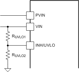
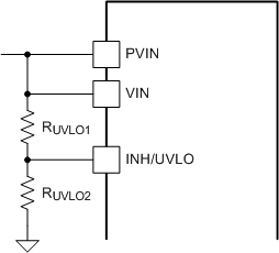
If an application requires either a higher UVLO threshold on the VIN pin or a higher UVLO threshold for a combined VIN and PVIN, then the UVLO pin can be configured as shown in Figure 39 or Figure 40. Table 8 lists standard values for RUVLO1 and RUVLO2 to adjust the VIN UVLO voltage up.
 Figure 39. Adjustable VIN UVLO
  Figure 40. Adjustable VIN and PVIN Undervoltage Lockout
 Table 8. Standard Resistor values for Adjusting VIN UVLO
| VIN UVLO (V) | 5.0 | 5.5 | 6.0 | 6.5 | 7.0 | 7.5 | 8.0 | 8.5 | 9.0 | 9.5 | 10.0 |
|---|---|---|---|---|---|---|---|---|---|---|---|
| RUVLO1 (kΩ) | 68.1 | 68.1 | 68.1 | 68.1 | 68.1 | 68.1 | 68.1 | 68.1 | 68.1 | 68.1 | 68.1 |
| RUVLO2 (kΩ) | 21.5 | 18.7 | 16.9 | 15.4 | 14.0 | 13.0 | 12.1 | 11.3 | 10.5 | 9.76 | 9.31 |
| Hysteresis (mV) | 400 | 415 | 430 | 450 | 465 | 480 | 500 | 515 | 530 | 550 | 565 |
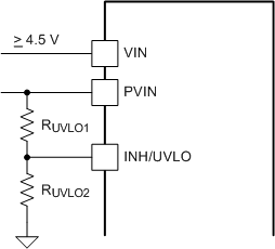
For a split rail application, if a secondary UVLO on PVIN is required, VIN must be ≥ 4.5 V. Figure 41 shows the PVIN UVLO configuration. Use Table 9 to select RUVLO1 and RUVLO2 for PVIN. If PVIN UVLO is set for less than 3.5 V, a 5.1-V zener diode should be added to clamp the voltage on the UVLO pin below 6 V.
 Figure 41. Adjustable PVIN Undervoltage Lockout, (VIN ≥ 4.5 V)
 Table 9. Standard Resistor Values for Adjusting PVIN UVLO, (VIN ≥ 4.5 V)
| PVIN UVLO (V) | 2.9 | 3.0 | 3.5 | 4.0 | 4.5 | |
|---|---|---|---|---|---|---|
| RUVLO1 (kΩ) | 68.1 | 68.1 | 68.1 | 68.1 | 68.1 | For higher PVIN UVLO voltages, see Table 8 for resistor values |
| RUVLO2 (kΩ) | 47.5 | 44.2 | 34.8 | 28.7 | 24.3 | |
| Hysteresis (mV) | 330 | 335 | 350 | 365 | 385 |