ZHCS581H February 2011 – November 2014 LM5046
PRODUCTION DATA.
- 1 特性
- 2 应用
- 3 说明
- 4 修订历史记录
- 5 Pin Configuration and Functions
- 6 Specifications
-
7 Detailed Description
- 7.1 Overview
- 7.2 Functional Block Diagram
- 7.3
Feature Description
- 7.3.1 High-Voltage Start-Up Regulator
- 7.3.2 Line Undervoltage Detector
- 7.3.3 Overvoltage Protection
- 7.3.4 Reference
- 7.3.5 Oscillator, Sync Input
- 7.3.6 Cycle-by-Cycle Current Limit
- 7.3.7 Hiccup Mode
- 7.3.8 PWM Comparator
- 7.3.9 RAMP Pin
- 7.3.10 Slope Pin
- 7.3.11 Soft-Start
- 7.3.12 Gate Driver Outputs
- 7.3.13 Synchronous Rectifier Control Outputs (SR1 & SR2)
- 7.3.14 Soft-Start of the Synchronous Rectifiers
- 7.3.15 Pre-Bias Startup
- 7.3.16 Soft-Stop
- 7.3.17 Soft-Stop Off
- 7.3.18 Thermal Protection
- 7.4 Device Functional Modes
-
8 Application and Implementation
- 8.1 Application Information
- 8.2
Typical Application
- 8.2.1 Design Requirements
- 8.2.2
Detailed Design Procedure
- 8.2.2.1 Phase-Shifted Full-Bridge Operation
- 8.2.2.2 Control Method Selection
- 8.2.2.3 Voltage Mode Control Using the LM5046
- 8.2.2.4 Current Mode Control Using the LM5046
- 8.2.2.5 VIN and VCC
- 8.2.2.6 For Applications With > 100 V Input
- 8.2.2.7 UVLO and OVP Voltage Divider Selection
- 8.2.2.8 Current Sense
- 8.2.2.9 Hiccup Mode Current Limit Restart
- 8.2.2.10 Augmenting the Gate Drive Strength
- 8.2.3 Application Curve
- 9 Power Supply Recommendations
- 10Layout
- 11器件和文档支持
- 12机械、封装和可订购信息
封装选项
机械数据 (封装 | 引脚)
散热焊盘机械数据 (封装 | 引脚)
- PWP|28
订购信息
1 特性
2 应用
- 电动自行车
- 军用:雷达/电子战
- 电源:电信 DC/DC 模块:模拟
- 专用分支交换机 (PBX)
- 太阳能逆变器
- 矢量信号发生器
- 微波炉
- 点对点微波回程
- 电源:电信/服务器 AC/DC 电源:双路控制器:模拟
- 太阳能微型逆变器
- 陆地集群无线电 (TETRA) 基站
- 洗衣机:低端
3 说明
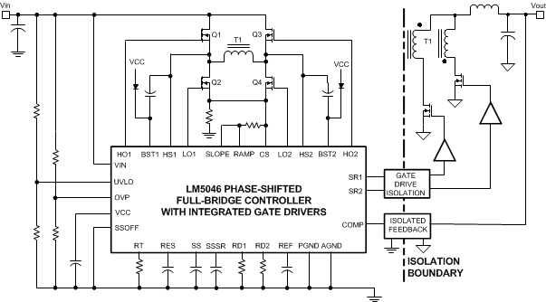
LM5046 脉宽调制 (PWM) 控制器具有 利用电流模式或电压模式控制实现相移全桥拓扑电源转换器 所需的全部功能。该器件可由输入电压最高可达 100V 的隔离式 DC-DC 转换器初级侧供电运行。这款高度集成的控制器 - 驱动器可为四个外部桥式金属氧化物半导体场效应晶体管 (MOSFET) 提供 2A 双路高侧和低侧栅极驱动器,同时为次级侧同步整流 MOSFET 提供控制信号。外部电阻通过编程方式设定死区,以启用初级侧场效应晶体管 (FET) 的零电压转换。由于同步整流器能够以智能方式启动,因此支持电源转换器单调导通,即使在预偏置负载条件下也是如此。其他 功能 包括逐周期电流限制、断续模式重启、可编程软启动、同步整流软启动和具有同步和热关断功能的 2MHz 振荡器。
器件信息(1)
| 器件型号 | 封装 | 封装尺寸(标称值) |
|---|---|---|
| LM5046 | HTSSOP (28) | 9.70 mm x 4.40 mm |
| WSON (28) | 5.00mm x 5.00mm |
- 要了解所有可用封装,请见数据表末尾的可订购产品附录。
简化的相移全桥电源转换器
