ZHCSFO2E December 1999 – December 2017 INA138 , INA168
PRODUCTION DATA.
- 1 特性
- 2 应用
- 3 说明
- 4 修订历史记录
- 5 Pin Configuration and Functions
- 6 Specifications
- 7 Detailed Description
-
8 Application and Implementation
- 8.1 Application Information
- 8.2 Typical Applications
- 9 Power Supply Recommendations
- 10Layout
- 11器件和文档支持
- 12机械、封装和可订购信息
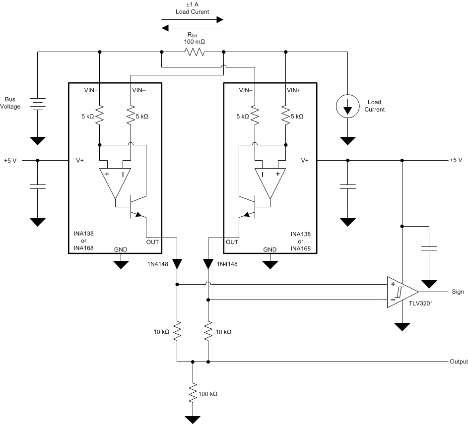
8.2.4 Bipolar Current Measurement
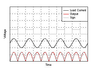
The INA1x8 devices can be configured as shown in Figure 15 in applications where measuring current bi-directionally is required. Two INA devices are required connecting their inputs across the shunt resistor as shown in Figure 15. A comparator, such as the TLV3201, is used to detect the polarity of the load current. The magnitude of the load current is monitored across the resistor connected between ground and the connection labeled Output. In this example the 100-kΩ resistor results in a gain of 20 V/V. The 10-kΩ resistors connected in series with the INA1x8 output current are used to develop a voltage across the comparator inputs. Two diodes are required to prevent current flow into the INA1x8 output, as only one device at a time is providing current to the Output connection of the circuit. The circuit functionality is illustrated in Figure 16.
 Figure 15. Bipolar Current Measurement
 Figure 16. Bipolar Current Measurements Results (arbitrary scale)