ZHCSG92A June 2014 – March 2017 DRV8846
PRODUCTION DATA.
- 1 特性
- 2 应用
- 3 说明
- 4 修订历史记录
- 5 Pin Configuration and Functions
- 6 Specifications
- 7 Detailed Description
- 8 Application and Implementation
- 9 Power Supply Recommendations
- 10Layout
- 11器件和文档支持
- 12机械、封装和可订购信息
封装选项
机械数据 (封装 | 引脚)
- RGE|24
散热焊盘机械数据 (封装 | 引脚)
- RGE|24
订购信息
8 Application and Implementation
NOTE
Information in the following applications sections is not part of the TI component specification, and TI does not warrant its accuracy or completeness. TI’s customers are responsible for determining suitability of components for their purposes. Customers should validate and test their design implementation to confirm system functionality.
8.1 Application Information
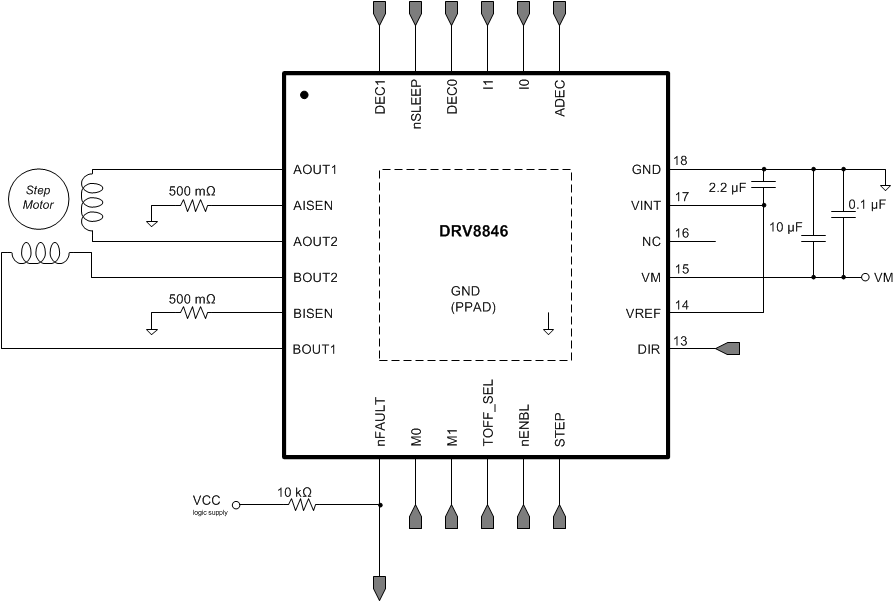
The DRV8846 is used in stepper motor control.
8.2 Typical Application
The following design procedure can be used to configure the DRV8846.

8.2.1 Design Requirements
Table 11 gives design input parameters for system design.
Table 11. System Design Input Parameters
| DESIGN PARAMETER | REFERENCE | EXAMPLE VALUE |
|---|---|---|
| Nominal supply voltage | VM | 12 V |
| Supply voltage range | 4 to 18 V | |
| Motor winding resistance | RL | 3.0 Ω/phase |
| Motor winding inductance | LL | 330 µH/phase |
| Motor full step angle | θstep | 1.8°/step |
| Target stepping level | nm | 1/8 step |
| Target motor speed | v | 400 rpm |
| Target chopping current | ICHOP | 500 mA |
| Chopping current reference voltage | VREF | 3.3 V |
| Current scaling | TORQUE | 100% |
8.2.2 Detailed Design Procedure
8.2.2.1 Stepper Motor Speed
The first step in configuring the DRV8846 requires the desired motor speed and stepping level. The DRV8846 can support from full step to 1/32 step mode.
If the target motor speed is too high, the motor will not spin. Make sure that the motor can support the target speed.
For a desired motor speed (v), microstepping level (nm), and motor full step angle (θstep),

θstep can be found in the stepper motor data sheet or often written on the motor itself.
For DRV8846, the microstepping levels are set by the M0/M1 pins and can be any of the settings in Table 2. Higher microstepping means a smoother motor motion and less audible noise, but increases the switching losses and requires a higher ƒstep to achieve the same motor speed.
8.2.2.2 Current Regulation
The chopping current (ICHOP) is the maximum current driven through either winding. This quantity will depend on the sense resistor value (RXISEN).

ICHOP is set by a comparator which compares the voltage across RXISEN to a reference voltage. Note that ICHOP must follow Equation 4 to avoid saturating the motor.

where
- VM is the motor supply voltage.
- RL is the motor winding resistance.
8.2.2.3 Decay Modes
The DRV8846 supports four different decay modes: slow decay, fast decay, mixed decay, and AutoTune. The first selection to try is the AutoTune mode, which adjusts the decay mode automatically to improve current regulation. The current through the motor windings is regulated using a fixed-off-time PWM scheme. This means that after any drive phase, when a motor has reached the current chopping threshold (ICHOP), the DRV8846 places the motor in one of the four decay modes until the PWM cycle has expired. Afterward, a new drive phase starts.
The blanking time, tBLANK, defines the minimum drive time for the current chopping. ICHOP is ignored during tBLANK, so the winding current may overshoot the trip level during this blanking period.
8.2.3 Application Curves
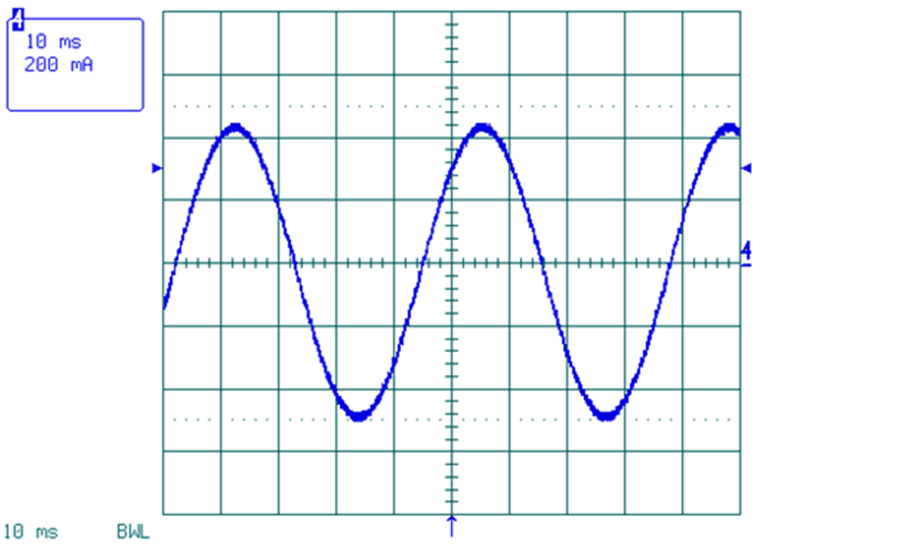
 Figure 13. Microstepping Waveform, Phase A, AutoTune
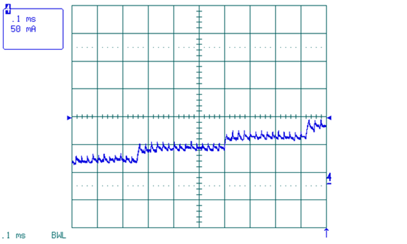
 Figure 14. Microstepping Waveform, AutoTune, Step Current Regulation