ZHCSCE2I October   2013  – March 2022 BQ76920 , BQ76930 , BQ76940

PRODMIX  

  1. 特性
  2. 应用
  3. 说明
  4. Revision History
  5. Device Comparison Table
  6. Pin Configuration and Functions
    1. 6.1 Versions
    2. 6.2 BQ76920 Pin Diagram
    3. 6.3 BQ76930 Pin Diagram
    4. 6.4 BQ76940 Pin Diagram
  7. Specifications
    1. 7.1 Absolute Maximum Ratings
    2. 7.2 ESD Ratings
    3. 7.3 Recommended Operating Conditions
    4. 7.4 Thermal Information
    5. 7.5 Electrical Characteristics
    6. 7.6 Timing Requirements
    7. 7.7 Typical Characteristics
  8. Detailed Description
    1. 8.1 Overview
    2. 8.2 Functional Block Diagram
    3. 8.3 Feature Description
      1. 8.3.1 Subsystems
        1. 8.3.1.1 Measurement Subsystem Overview
          1. 8.3.1.1.1 Data Transfer to the Host Controller
          2. 8.3.1.1.2 14-Bit ADC
            1. 8.3.1.1.2.1 Optional Real-Time Calibration Using the Host Microcontroller
          3. 8.3.1.1.3 16-Bit CC
          4. 8.3.1.1.4 External Thermistor
          5. 8.3.1.1.5 Die Temperature Monitor
          6. 8.3.1.1.6 16-Bit Pack Voltage
          7. 8.3.1.1.7 System Scheduler
        2. 8.3.1.2 Protection Subsystem
          1. 8.3.1.2.1 Integrated Hardware Protections
          2. 8.3.1.2.2 Reduced Test Time
        3. 8.3.1.3 Control Subsystem
          1. 8.3.1.3.1 FET Driving (CHG AND DSG)
            1. 8.3.1.3.1.1 High-Side FET Driving
          2. 8.3.1.3.2 Load Detection
          3. 8.3.1.3.3 Cell Balancing
          4. 8.3.1.3.4 Alert
          5. 8.3.1.3.5 Output LDO
        4. 8.3.1.4 Communications Subsystem
    4. 8.4 Device Functional Modes
      1. 8.4.1 NORMAL Mode
      2. 8.4.2 SHIP Mode
    5. 8.5 Register Maps
      1. 8.5.1 Register Details
      2. 8.5.2 Read-Only Registers
  9. Application and Implementation
    1. 9.1 Application Information
      1. 9.1.1 Device Timing
      2. 9.1.2 Random Cell Connection
      3. 9.1.3 Power Pin Diodes
      4. 9.1.4 Alert Pin
      5. 9.1.5 Sense Inputs
      6. 9.1.6 TSn Pins
      7. 9.1.7 Unused Pins
      8. 9.1.8 Configuring Alternative Cell Counts
    2. 9.2 Typical Applications
      1. 9.2.1 Design Requirements
      2. 9.2.2 Detailed Design Procedure
        1. 9.2.2.1 Step-by-Step Design Procedure
      3. 9.2.3 Application Curves
  10. 10Power Supply Recommendations
  11. 11Layout
    1. 11.1 Layout Guidelines
    2. 11.2 Layout Example
  12. 12Device and Documentation Support
    1. 12.1 第三方产品免责声明
    2. 12.2 Documentation Support
    3. 12.3 Related Links
    4. 12.4 Receiving Notification of Documentation Updates
    5. 12.5 Trademarks
  13. 13Mechanical, Packaging, and Orderable Information

封装选项

机械数据 (封装 | 引脚)
散热焊盘机械数据 (封装 | 引脚)
订购信息

说明

BQ769x0 可靠的模拟前端 (AFE) 器件系列是针对下一代高功率系统(如轻型电动车辆、电动工具和不间断电源)的完整电池组监控与保护解决方案的组成部分。BQ769x0 专为实现低功耗而设计:不仅可通过启用/禁用 IC 中的子块来控制整个芯片的电流消耗,还可以利用运输模式将电池组轻松切换至超低功耗状态。

BQ76920 器件支持多达 5 节串联电池或典型值为 18 V 的电池组,BQ76930 可处理多达 10 节串联电池或典型值为 36 V 的电池组,而 BQ76940 支持多达 15 节串联电池或典型值为 48 V 的电池组。可借助这些 AFE 管理各种电池化学物质,例如锂离子、磷酸铁锂等。通过 I2C,主机控制器可以使用 BQ769x0 来执行多种电池组管理功能,例如监控(电池电压、电池组电流、电池组温度)、保护(控制充电/放电 FET)以及平衡功能。集成式模数 (A/D) 转换器可实现对关键系统参数的纯数字读取,并会在 TI 制造过程中校准这些参数。

器件信息
器件型号1 封装 封装尺寸(标称值)
BQ76920 TSSOP (20) 6.50mm × 4.40mm
BQ76930 TSSOP (30) 7.80mm x 4.40mm
BQ76940 TSSOP (44) 11.00mm x 4.40mm
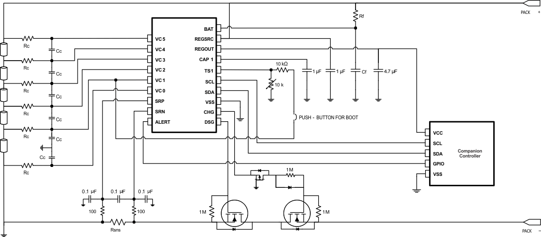
GUID-D43C0A72-3794-4621-A0EC-1876DBC0DE55-low.gif简化版原理图