ZHCSE30C August   2015  – September 2016 BQ25120 , BQ25121

PRODUCTION DATA.  

  1. 特性
  2. 应用
  3. 说明
    1.     简化原理图
  4. 修订历史记录
  5. 说明 (续)
  6. Device Comparison Table
  7. Pin Configuration and Functions
    1.     Pin Functions
  8. Specifications
    1. 8.1 Absolute Maximum Ratings
    2. 8.2 ESD Ratings
    3. 8.3 Recommended Operating Conditions
    4. 8.4 Thermal Information
    5. 8.5 Electrical Characteristics
    6. 8.6 Timing Requirements
    7. 8.7 Typical Characteristics
  9. Detailed Description
    1. 9.1 Overview
    2. 9.2 Functional Block Diagram
    3. 9.3 Feature Description
      1. 9.3.1  Ship Mode
      2. 9.3.2  High Impedance Mode
      3. 9.3.3  Active Battery Only Connected
      4. 9.3.4  Voltage Based Battery Monitor
      5. 9.3.5  Sleep Mode
      6. 9.3.6  Input Voltage Based Dynamic Power Management (VIN(DPM))
      7. 9.3.7  Input Overvoltage Protection and Undervoltage Status Indication
      8. 9.3.8  Battery Charging Process and Charge Profile
      9. 9.3.9  Dynamic Power Path Management Mode
      10. 9.3.10 Battery Supplement Mode
      11. 9.3.11 Default Mode
      12. 9.3.12 Termination and Pre-Charge Current Programming by External Components (IPRETERM)
      13. 9.3.13 Input Current Limit Programming by External Components (ILIM)
      14. 9.3.14 Charge Current Programming by External Components (ISET)
      15. 9.3.15 Safety Timer and Watchdog Timer
      16. 9.3.16 External NTC Monitoring (TS)
      17. 9.3.17 Thermal Protection
      18. 9.3.18 Typical Application Power Dissipation
      19. 9.3.19 Status Indicators (PG and INT)
      20. 9.3.20 Chip Disable (CD)
      21. 9.3.21 Buck (PWM) Output
      22. 9.3.22 Load Switch / LDO Output and Control
      23. 9.3.23 Manual Reset Timer and Reset Output (MR and RESET)
    4. 9.4 Device Functional Modes
    5. 9.5 Programming
      1. 9.5.1 Serial Interface Description
      2. 9.5.2 F/S Mode Protocol
    6. 9.6 Register Maps
      1. 9.6.1  Status and Ship Mode Control Register
        1. Table 12. Status and Ship Mode Control Register
      2. 9.6.2  Faults and Faults Mask Register
        1. Table 13. Faults and Faults Mask Register
      3. 9.6.3  TS Control and Faults Masks Register
        1. Table 14. TS Control and Faults Masks Register, Memory Location 0010
      4. 9.6.4  Fast Charge Control Register
        1. Table 15. Fast Charge Control Register
      5. 9.6.5  Termination/Pre-Charge and I2C Address Register
        1. Table 16. Termination/Pre-Charge and I2C Address Register
      6. 9.6.6  Battery Voltage Control Register
        1. Table 17. Battery Voltage Control Register
      7. 9.6.7  SYS VOUT Control Register
        1. Table 18. SYS VOUT Control Register
      8. 9.6.8  Load Switch and LDO Control Register
        1. Table 20. Load Switch and LDO Control Register
      9. 9.6.9  Push-button Control Register
        1. Table 21. Push-button Control Register
      10. 9.6.10 ILIM and Battery UVLO Control Register
        1. Table 22. ILIM and Battery UVLO Control Register, Memory Location 1001
      11. 9.6.11 Voltage Based Battery Monitor Register
        1. Table 23. Voltage Based Battery Monitor Register, Memory Location 1010
      12. 9.6.12 VIN_DPM and Timers Register
        1. Table 24. VIN_DPM and Timers Register
  10. 10Application and Implementation
    1. 10.1 Application Information
    2. 10.2 Typical Application
      1. 10.2.1 Design Requirements
      2. 10.2.2 Detailed Design Procedure
        1. 10.2.2.1 Default Settings
        2. 10.2.2.2 Choose the Correct Inductance and Capacitance
        3. 10.2.2.3 Calculations
          1. 10.2.2.3.1 Program the Fast Charge Current (ISET)
          2. 10.2.2.3.2 Program the Input Current Limit (ILIM)
          3. 10.2.2.3.3 Program the Pre-charge/termination Threshold (IPRETERM)
          4. 10.2.2.3.4 TS Resistors (TS)
      3. 10.2.3 Application Performance Curves
        1. 10.2.3.1 Charger Curves
        2. 10.2.3.2 SYS Output Curves
        3. 10.2.3.3 Load Switch and LDO Curves
        4. 10.2.3.4 LS/LDO Output Curves
        5. 10.2.3.5 Timing Waveforms Curves
  11. 11Power Supply Recommendations
  12. 12Layout
    1. 12.1 Layout Guidelines
    2. 12.2 Layout Example
  13. 13器件和文档支持
    1. 13.1 器件支持
      1. 13.1.1 第三方产品免责声明
    2. 13.2 相关链接
    3. 13.3 接收文档更新通知
    4. 13.4 社区资源
    5. 13.5 商标
    6. 13.6 静电放电警告
    7. 13.7 Glossary
  14. 14机械、封装和可订购信息

封装选项

机械数据 (封装 | 引脚)
散热焊盘机械数据 (封装 | 引脚)
订购信息

SYS Output Curves

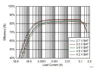
BQ25120 BQ25121 D001_SLUSBZ9.gif
TA = 25°C VSYS = 1.2 V
Figure 44. 1.2 VSYS System Efficiency
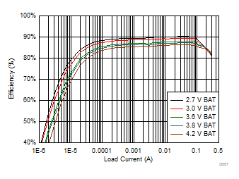
BQ25120 BQ25121 D007_SLUSBZ9.gif
TA = 25°C VSYS = 1.8 V
Figure 46. 1.8 VSYS System Efficiency
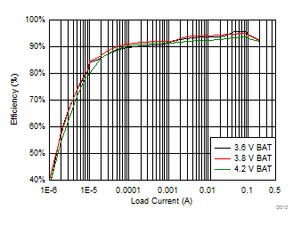
BQ25120 BQ25121 D013_SLUSBZ9.gif
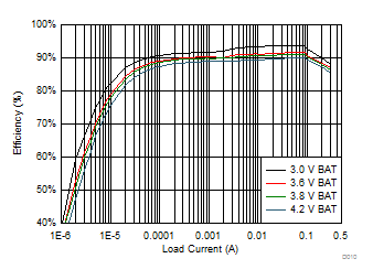
TA = 25°C VSYS = 3.3 V
Figure 48. 3.3 VSYS System Efficiency
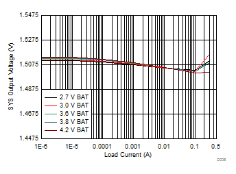
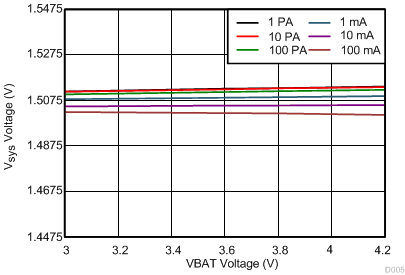
BQ25120 BQ25121 D006_SLUSBZ9.gif
TA = 25°C VSYS = 1.5 V
Figure 50. 1.5 VSYS Load Regulation
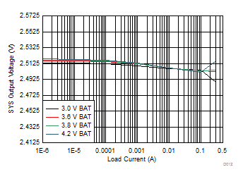
BQ25120 BQ25121 D012_SLUSBZ9.gif
TA = 25°C VSYS = 2.5 V
Figure 52. 2.5 VSYS Load Regulation
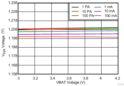
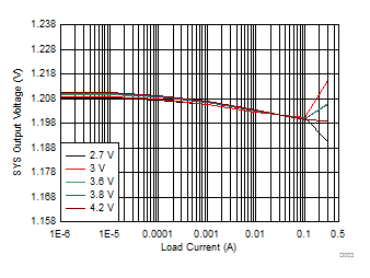
BQ25120 BQ25121 D002_SLUSBZ9.gif
TA = 25°C VSYS = 1.2 V
Figure 54. 1.2 VSYS Line Regulation
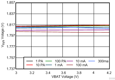
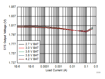
BQ25120 BQ25121 D008_SLUSBZ9.gif
TA = 25°C VSYS = 1.8 V
Figure 56. 1.8 VSYS Line Regulation
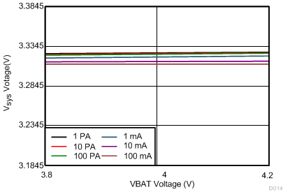
BQ25120 BQ25121 D014_SLUSBZ9.gif
TA = 25°C VSYS = 3.3 V
Figure 58. 3.3 VSYS Line Regulation
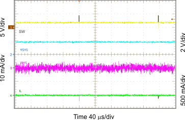
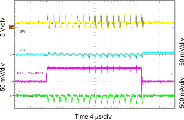
BQ25120 BQ25121 G010_slusbz9.gif
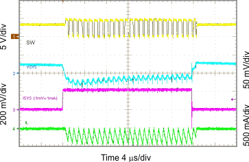
ILOAD = 10 µA
Figure 60. Light Load Operation Showing SW
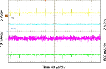
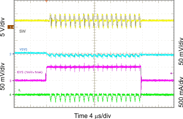
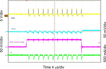
BQ25120 BQ25121 G012_slusbz9.gif
ILOAD = 1 mA
Figure 62. Light Load Operation Showing SW
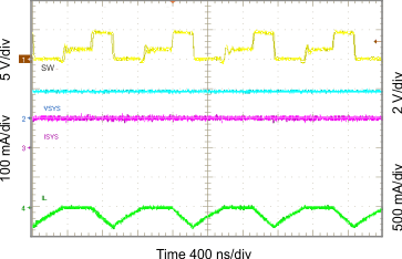
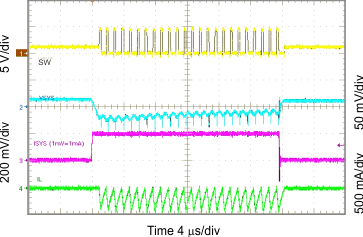
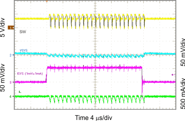
BQ25120 BQ25121 G014_slusbz9.gif
ILOAD = 100 mA
Figure 64. Light Load Operation Showing SW
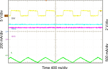
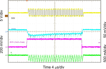
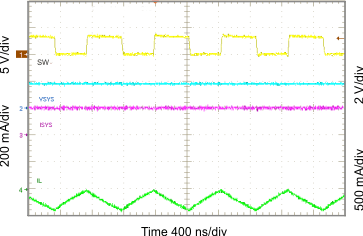
BQ25120 BQ25121 G016_slusbz9.gif
ILOAD = 300 mA
Figure 66. Light Load Operation Showing SW
BQ25120 BQ25121 G018_slusbz9.gif
VSYS = 1.8 V
Figure 68. 1.8 VSYS Load Transient, 0 to 50 mA
BQ25120 BQ25121 G020_slusbz9.gif
VSYS = 2.5 V
Figure 70. 2.5 VSYS Load Transient, 0 to 50 mA
BQ25120 BQ25121 G022_slusbz9.gif
VSYS = 1.2 V
Figure 72. 1.2 VSYS Load Transient, 0 to 200 mA
BQ25120 BQ25121 G024_slusbz9.gif
VSYS = 2.1 V
Figure 74. 2.1 VSYS Load Transient, 0 to 200 mA
BQ25120 BQ25121 G026_slusbz9.gif
VSYS = 3.3 V
Figure 76. 3.3 VSYS Load Transient, 0 to 200 mA
BQ25120 BQ25121 G028_slusbz9.gif
Figure 78. Short Circuit and Recovery for SYS
BQ25120 BQ25121 D004_SLUSBZ9.gif
TA = 25°C VSYS = 1.5 V
Figure 45. 1.5 VSYS System Efficiency
BQ25120 BQ25121 D010_SLUSBZ9.gif
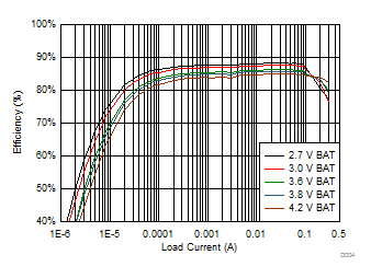
TA = 25°C VSYS = 2.5 V
Figure 47. 2.5 VSYS System Efficiency
BQ25120 BQ25121 D003_SLUSBZ9.gif
TA = 25°C VSYS = 1.2 V
Figure 49. 1.2 VSYS Load Regulation
BQ25120 BQ25121 D009_SLUSBZ9.gif
TA = 25°C VSYS = 1.8 V
Figure 51. 1.8 VSYS Load Regulation
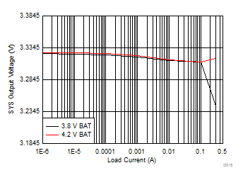
BQ25120 BQ25121 D015_SLUSBZ9.gif
TA = 25°C VSYS = 3.3 V
Figure 53. 3.3 VSYS Load Regulation
BQ25120 BQ25121 D005_SLUSBZ9.gif
TA = 25°C VSYS = 1.5 V
Figure 55. 1.5 VSYS Line Regulation
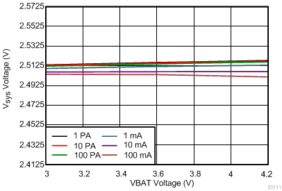
BQ25120 BQ25121 D011_SLUSBZ9.gif
TA = 25°C VSYS = 2.1 V
Figure 57. 2.1 VSYS Line Regulation
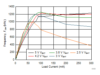
BQ25120 BQ25121 D023_SLUSBZ9.gif
Figure 59. 1.8 VSYS Switching Frequency vs Load Current
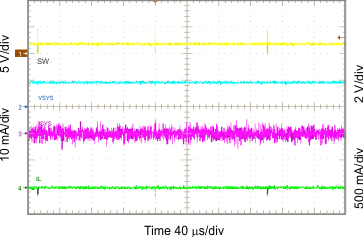
BQ25120 BQ25121 G011_slusbz9.gif
ILOAD = 100 mA
Figure 61. Light Load Operation Showing SW
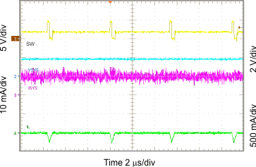
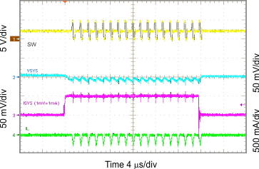
BQ25120 BQ25121 G013_slusbz9.gif
ILOAD = 10 mA
Figure 63. Light Load Operation Showing SW
BQ25120 BQ25121 G015_slusbz9.gif
ILOAD = 200 mA
Figure 65. Light Load Operation Showing SW
BQ25120 BQ25121 G017_slusbz9.gif
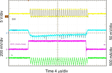
VSYS = 1.2 V
Figure 67. 1.2 VSYS Load Transient, 0 to 50 mA
BQ25120 BQ25121 G019_slusbz9.gif
VSYS = 2.1 V
Figure 69. 2.1 VSYS Load Transient, 0 to 50 mA
BQ25120 BQ25121 G021_slusbz9.gif
VSYS = 3.3 V
Figure 71. 3.3 VSYS Load Transient, 0 to 50 mA
BQ25120 BQ25121 G023_slusbz9.gif
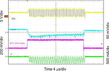
VSYS = 1.8 V
Figure 73. 1.8 VSYS Load Transient, 0 to 200 mA
BQ25120 BQ25121 G025_slusbz9.gif
VSYS = 2.5 V
Figure 75. 2.5 VSYS Load Transient, 0 to 200 mA
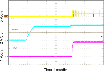
BQ25120 BQ25121 G027_slusbz9.gif
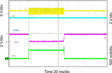
Figure 77. Startup Showing SS on SYS in PWM Mode