ZHCSKO6B July 2010 – January 2020 BQ24650
PRODUCTION DATA.
- 1 特性
- 2 应用
- 3 说明
- 4 修订历史记录
- 5 说明 (续)
- 6 Pin Configuration and Functions
- 7 Specifications
-
8 Detailed Description
- 8.1 Overview
- 8.2 Functional Block Diagram
- 8.3
Feature Description
- 8.3.1 Battery Voltage Regulation
- 8.3.2 Input Voltage Regulation
- 8.3.3 Battery Current Regulation
- 8.3.4 Battery Precharge
- 8.3.5 Charge Termination and Recharge
- 8.3.6 Power Up
- 8.3.7 Enable and Disable Charging
- 8.3.8 Automatic Internal Soft-Start Charger Current
- 8.3.9 Converter Operation
- 8.3.10 Synchronous and Non-Synchronous Operation
- 8.3.11 Cycle-by-Cycle Charge Undercurrent
- 8.3.12 Input Overvoltage Protection (ACOV)
- 8.3.13 Input Undervoltage Lockout (UVLO)
- 8.3.14 Battery Overvoltage Protection
- 8.3.15 Cycle-by-Cycle Charge Overcurrent Protection
- 8.3.16 Thermal Shutdown Protection
- 8.3.17 Temperature Qualification
- 8.3.18 Charge Enable
- 8.3.19 Inductor, Capacitor, and Sense Resistor Selection Guidelines
- 8.3.20 Charge Status Outputs
- 8.3.21 Battery Detection
- 8.4 Device Functional Modes
- 9 Application and Implementation
- 10Power Supply Recommendations
- 11Layout
- 12器件和文档支持
- 13机械、封装和可订购信息
8.3.1 Battery Voltage Regulation
The BQ24650 uses a high accuracy voltage regulator for the charging voltage. The charge voltage is programmed through a resistor divider from the battery to ground, with the midpoint tied to the VFB pin. The voltage at the VFB pin is regulated to 2.1 V, giving Equation 1 for the regulation voltage:

where
- R2 is connected from VFB to the battery
- and R1 is connected from VFB to GND.
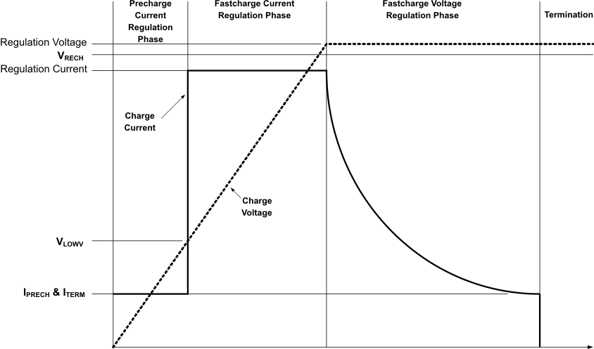
Li-Ion, LiFePO4, and sealed lead acid are widely used battery chemistries. Most commercial Li-ion cells can now be charged to 4.2 V/cell. A LiFePO4 battery allows a much higher charge and discharge rate, but the energy density is lower. The typical cell voltage is 3.6 V. The charge profile of both Li-Ion and LiFePO4 is preconditioning, constant current, and constant voltage. For maximum cycle life, the end-of-charge voltage threshold could be lowered to 4.1 V/cell.
Although the energy density is much lower than Li-based chemistry, lead acid is still popular due to its low manufacturing cost and high discharge rates. The typical voltage limit is from 2.3 V to 2.45 V. After the battery has been fully charged, a float charge is required to compensate for the self-discharge. The float charge limit is 100 mV to 200 mV below the constant voltage limit.
 Figure 9. Typical Charging Profile