ZHCSEU3E July 2014 – June 2022 ADC3221 , ADC3222 , ADC3223 , ADC3224
PRODUCTION DATA
- 1 特性
- 2 应用
- 3 说明
- 4 Revision History
- 5 Pin Configuration and Functions
-
6 Specifications
- 6.1 Absolute Maximum Ratings
- 6.2 ESD Ratings
- 6.3 Recommended Operating Conditions (1)
- 6.4 Thermal Information
- 6.5 Electrical Characteristics: General
- 6.6 Electrical Characteristics: ADC3221, ADC3222
- 6.7 Electrical Characteristics: ADC3223, ADC3224
- 6.8 AC Performance: ADC3221
- 6.9 AC Performance: ADC3222
- 6.10 AC Performance: ADC3223
- 6.11 AC Performance: ADC3224
- 6.12 Digital Characteristics
- 6.13 Timing Requirements: General
- 6.14 Timing Requirements: LVDS Output
- 6.15 Typical Characteristics: ADC3221
- 6.16 Typical Characteristics: ADC3222
- 6.17 Typical Characteristics: ADC3223
- 6.18 Typical Characteristics: ADC3224
- 6.19 Typical Characteristics: Common
- 6.20 Typical Characteristics: Contour
- 7 Parameter Measurement Information
-
8 Detailed Description
- 8.1 Overview
- 8.2 Functional Block Diagram
- 8.3 Feature Description
- 8.4 Device Functional Modes
- 8.5 Programming
- 8.6
Register Maps
- 8.6.1 Summary of Special Mode Registers
- 8.6.2
Serial Register Description
- 8.6.2.1 Register 01h
- 8.6.2.2 Register 03h
- 8.6.2.3 Register 04h
- 8.6.2.4 Register 05h
- 8.6.2.5 Register 06h
- 8.6.2.6 Register 07h
- 8.6.2.7 Register 09h
- 8.6.2.8 Register 0Ah
- 8.6.2.9 Register 0Bh
- 8.6.2.10 Register 0Eh
- 8.6.2.11 Register 0Fh
- 8.6.2.12 Register 13h
- 8.6.2.13 Register 15h
- 8.6.2.14 Register 25h
- 8.6.2.15 Register 27h
- 8.6.2.16 Register 41Dh
- 8.6.2.17 Register 422h
- 8.6.2.18 Register 434h
- 8.6.2.19 Register 439h
- 8.6.2.20 Register 51Dh
- 8.6.2.21 Register 522h
- 8.6.2.22 Register 534h
- 8.6.2.23 Register 539h
- 8.6.2.24 Register 608h
- 8.6.2.25 Register 70Ah
- 9 Applications and Implementation
- 10Device and Documentation Support
- 11Mechanical, Packaging, and Orderable Information
3 说明
ADC322x 属于高线性度、超低功耗、双通道、12 位、25MSPS 至 125MSPS 模数转换器 (ADC) 系列。此类器件专门设计用于支持具有宽动态范围需求且要求苛刻的高输入频率信号。当 SYSREF 输入实现整个系统同步时,时钟输入分频器将给予系统时钟架构设计更高的灵活性。ADC322x 系列支持串行低压差分信号 (LVDS),从而减少接口线路的数量,实现高系统集成度。串行 LVDS 接口为双线制,每种 ADC 数据采用串行形式并通过两个 LVDS 对输出。此外,还提供单线制串行 LVDS 接口。内部锁相环 (PLL) 会将传入的 ADC 采样时钟加倍,以获得串行输出各通道的 12 位输出数据时所使用的位时钟。除了串行数据流之外,数据帧和位时钟也作为 LVDS 输出进行传送。
封装信息
| 器件型号 | 封装(1) | 封装尺寸(标称值) |
|---|---|---|
| ADC322x | VQFN (48) | 7.00mm × 7.00mm |
(1) 如需了解所有可用封装,请参阅数据表末尾的可订购产品附录。
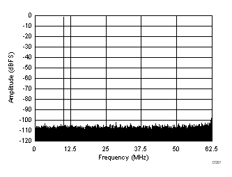
 fS = 125MSPS 且 fIN = 10MHz 时的性能
(SNR = 70.6dBFS,SFDR = 100dBc)