ZHCSAL0D March 2016 – August 2020 TPD3S716-Q1
PRODUCTION DATA
- 1 特性
- 2 应用
- 3 说明
- 4 Revision History
- 5 Pin Configuration and Functions
- 6 Specifications
- 7 Parameter Measurement Information
-
8 Detailed Description
- 8.1 Overview
- 8.2 Functional Block Diagram
- 8.3
Feature Description
- 8.3.1 AEC-Q100 Qualified
- 8.3.2 Short-to-Battery and Short-to-Ground Protection on VBUS_CON
- 8.3.3 Short-to-Battery and Short-to-VBUS Protection on VD+, VD–
- 8.3.4 ESD Protection on VBUS_CON, VD+, VD–
- 8.3.5 Low RON nFET VBUS Switch
- 8.3.6 High Speed Data Switches
- 8.3.7 Adjustable Hiccup Current Limit up to 2.4-A
- 8.3.8 Fast Over-Voltage Response Time
- 8.3.9 Independent VBUS and Data Enable Pins for Configuring both Host and Client/OTG Mode
- 8.3.10 Fault Output Signal
- 8.3.11 Thermal Shutdown Feature
- 8.3.12 16-Pin SSOP Package
- 8.3.13 Reverse Current Detection
- 8.4 Device Functional Modes
- 9 Application and Implementation
- 10Power Supply Recommendations
- 11Layout
- 12Device and Documentation Support
- 13Mechanical, Packaging, and Orderable Information
3 说明
TPD3S716-Q1 是一套具有可调节电流限制功能的单芯片解决方案,可为汽车应用中 USB 连接器的 VBUS 和数据线路提供电池短路保护、短路保护以及 ESD 保护。集成的数据开关提供了出色的带宽,能够在提供 18V 电池短路保护的同时最大限度地减少信号衰减。该器件具有 1GHz 的高带宽,适用于一些采用 USB2.0 高速数据速率的应用,如 Car Play。此外,该器件还具有 720MHz 以上的附加带宽裕量,有助于保持一个干净的 USB 2.0 眼图,并且支持使用较长的不可分离电缆(常见于汽车 USB 环境中)。电池短路保护可将内部系统电路隔离,防止其受到 VBUS_CON、VD+ 和 VD– 引脚上的任何过压情况的影响。在这些引脚上,TPD3S716-Q1 能够处理高达 18V 的过压情况(热插拔和直流事件)。过压保护电路可提供业内一流的电池短路保护,能够极为可靠地关断数据开关以保护上游电路免遭有害电压和电流尖峰的影响。
VBUS_CON 引脚还提供可调节的电流限制负载开关以及接地短路保护功能。该器件支持高达 2.4A 的 VBUS 电流,支持 USB BC1.2、USB Type-C 5V/1.5A 以及最高达 2.4A 的专用充电方案。独立的数据和 VBUS 使能引脚可用于配置主机和客户端-OTG 模式。此外,TPD3S716-Q1 还在 VBUS_CON、VD+ 和 VD– 引脚上集成了系统级 IEC 61000-4-2 和 ISO 10605 ESD 保护,无需使用高电压、低容值的外部二极管。
| 器件型号 | 封装 | 封装尺寸(标称值) |
|---|---|---|
| TPD3S716-Q1 | SSOP (16) | 4.90mm × 3.90mm |
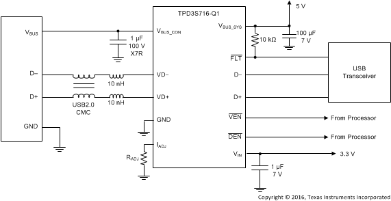
 典型应用原理图