TIDT334 September 2023 UCD3138
3.4 Overcurrent Protection
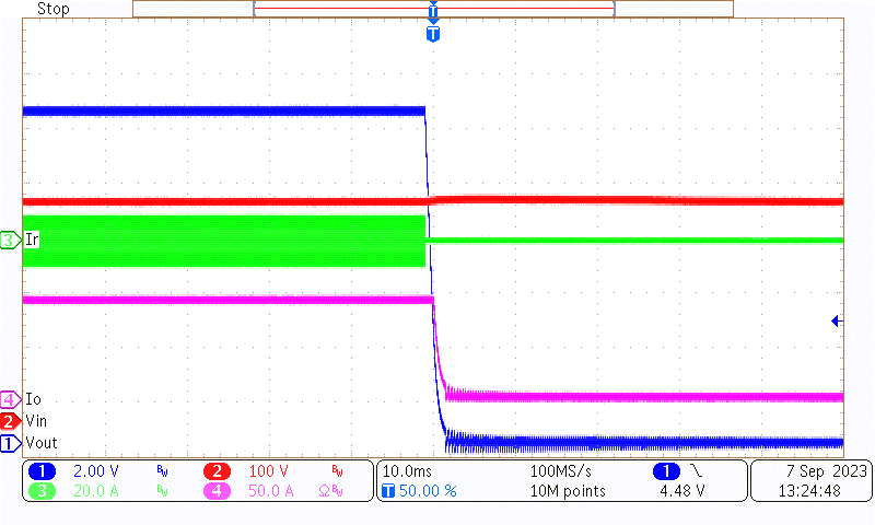
When the load current is over 90 A, the power stage is shut down by the current sensing protection with a short period. Figure 3-34 shows the waveform. Channel 1 is VOUT, channel 2 is VIN, channel 3 is Ir, channel 4 is IO.
 Figure 3-20 Overcurrent Protection (90 A)
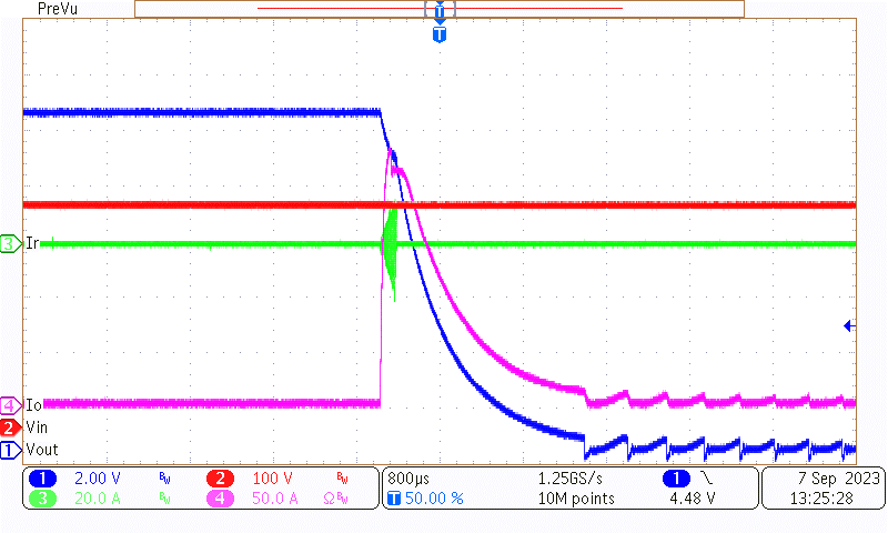
When the load current exceeds the internal comparator threshold, the power stage is shutdown by internal comparator protection with a faster speed. Figure 3-21 shows the waveform. Channel 1 is VOUT, channel 2 is VIN, channel 3 is Ir, channel 4 is IO.
 Figure 3-21 Shoot Protection (140 A)