SSZTA63 may 2017 CSD88584Q5DC , CSD88599Q5DC , DRV8323R
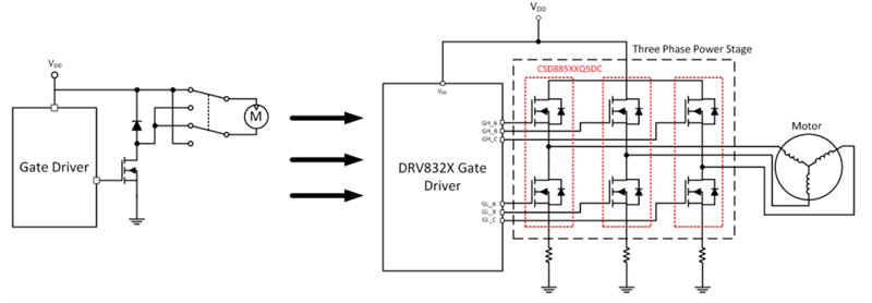
There has been a big shift in the preferred configuration for DC motors in power tools away from brushed DC toward more reliable and efficient brushless DC (BLDC) solutions. Typical brushed DC topologies like chopper configurations often implement one or two power metal-oxide semiconductor field-effect transistors (MOSFETs), depending on the use (or not) of bidirectional switching. Three-phase BLDC configurations, on the other hand, require three half bridges or a minimum of six FETs, so the move toward brushed to brushless means a 3x to 6x multiplier in the global power tool FET total area market (see Figure 1). As someone whose job it is to promote TI’s NexFET™ power MOSFETs, I can hardly complain about this market trend.
 Figure 1 The Transition from Brushed to
Brushless Topologies Can Mean a 6x Multiplier in the Number of FETs
Figure 1 The Transition from Brushed to
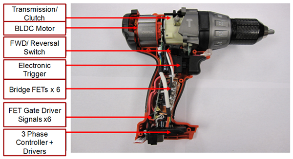
Brushless Topologies Can Mean a 6x Multiplier in the Number of FETsBLDC designs place new technical requirements on these FETs, however. For instance, if a 6x multiplier in the number of FETs on the board also implies a 6x increase in the printed circuit board (PCB) footprint required to drive a motor, it is unlikely that BLDC designs will remain appealing to power- and garden-tool manufacturers. Keep in mind that the power electronics are usually located in the handle of these tools; thus, the applications are generally very space-constrained in order to accommodate even the smallest hands (see Figure 2). There is a demand for higher-power-density solutions – or in other words, FETs that can handle more current in less space.
 Figure 2 In Most Power Tools, the
Electronics Are Located in the Handle
Figure 2 In Most Power Tools, the
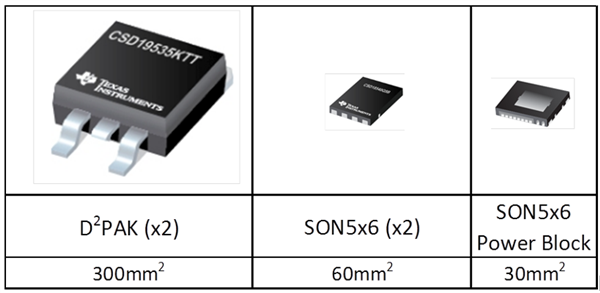
Electronics Are Located in the HandleHistorically, the FETs most popular for driving high-powered motors came in big, bulky packages like TO-220, DPAK and D2PAK. But newer quad flat no-lead (QFN) packages like TI’s small outline no-lead (SON) 5mm-by-6mm FETs offer less package resistance between the silicon die and source pin. Less resistance per unit area means less conduction losses per unit area, which means higher current capability and higher power density. It shouldn’t be surprising, then, that as resistance per unit area (RSP) of FET silicon continues to decrease (roughly halving itself with each passing generation), QFN solutions in the power-tool, garden-tool and home-appliance sectors have grown rapidly. These smaller FETs are now often capable of driving DC motor currents as high as 30A or more on their own; even for higher power designs, paralleling multiple QFNs is sometimes preferable to resorting back to the larger packages. After all, two 5mm-by-6mm devices at 60mm2 of total PCB space are still just a fraction of the size of one D2PAK, which is roughly 10mm by 15mm at 150mm2 of total PCB space (see Figure 3).
 Figure 3 PCB Space Required for a Half
Bridge (Drawings Not to Scale)
Figure 3 PCB Space Required for a Half
Bridge (Drawings Not to Scale)TI has recently taken this trend to its logical conclusion by vertically integrating two FETs into a single package, offering the entire half bridge in one SON 5mm-by-6mm power block. The 40V CSD88584Q5DC and 60V CSD88599Q5DC use the same stacked die technology as TI’s lower-voltage power blocks for high-frequency power-supply applications, but with optimized silicon die to minimize the conduction losses for high-current motor-drive applications. In addition to minimizing the parasitic inductances that come from having two FETs side by side on the PCB, vertically integrating two FETs enables the housing of more silicon in the same package, thus achieving even higher power density than discrete QFN devices.
These devices also come in a thermally enhanced DualCool™ package with an exposed metal top. So while there are still some instances where a power-tool manufacturer may prefer TO-220 FETs to surface-mount FETs because those FETs can be mounted on large heat sinks to pull heat away from the PCB, these power blocks offer the same benefit but in a QFN package. As an example, dissipating over 3W of power in a typical 5mm-by-6mm QFN is typically discouraged, even in the most ideal thermal environments. But with the proper application of a heat sink, these DualCool devices can handle 6W or more of power dissipation, at double the power density and half the PCB space.
When it comes to driving the more popular BLDC motors in today’s power and garden tools and battery-powered home appliances, power density is the name of the game. TI’s new power-block solutions can deliver on that front on an unprecedented level.
Additional Resources
- For more information about these new power blocks, check out the 18V/1kW, 160A Peak, >98% Efficient, High Power Density Brushless Motor Drive Reference Design, featuring the 40V CSD88584Q5DC.
- Order the DRV8323RH three-phase smart gate driver evaluation module featuring the 60V CSD88599Q5DC and DRV8323R gate driver.
- Check out a blog with the basics of brushless gate driver design.