SPRACV3 December 2020 AM6412 , AM6422 , AM6442
- Trademarks
- 1Simulations
-
2Models
- 2.1 IBIS-AMI Model Kit
- 2.2 The Kit Structure
- 2.3 Contents of the Kit
- 2.4 IBIS Analog Models
- 2.5
Algorithmic Models
- 2.5.1
Transmitter (Tx) Model
- 2.5.1.1 TX AMI Parameters for Gen 1
- 2.5.1.2 TX AMI Parameters for Gen 2
- 2.5.1.3 TX AMI Parameters for Gen 3
- 2.5.1.4 TX AMI Parameters for Sgmii
- 2.5.1.5 TX AMI Parameters for Qsgmii
- 2.5.1.6 TX AMI Parameters for USB3.0
- 2.5.1.7 TX AMI Parameters for USB3.1
- 2.5.1.8 TX AMI Parameters for USXGMII
- 2.5.1.9 TX AMI Parameters for Display Port
- 2.5.1.10 Transmitter Specifications
- 2.5.1.11 TX_Jitter Injection Parameters
- 2.5.2 Receiver (Rx) Model
- 2.5.1
Transmitter (Tx) Model
- 2.6 Valid Simulation Condition
- 2.7 Eye Mask Requirement
2.5.2.1 RX AMI Parameters
The Torrent16FFC RX AMI parameters are listed in Figure 2-9. These are for all supported speeds. Parameter descriptions are provided in Table 2-7.
Set the path of the data folder where companion files of Rx are kept at the ‘LIBPATH’ section of .ami file.
 Figure 2-9 Receiver Algorithmic Model
Parameters
Figure 2-9 Receiver Algorithmic Model
Parameters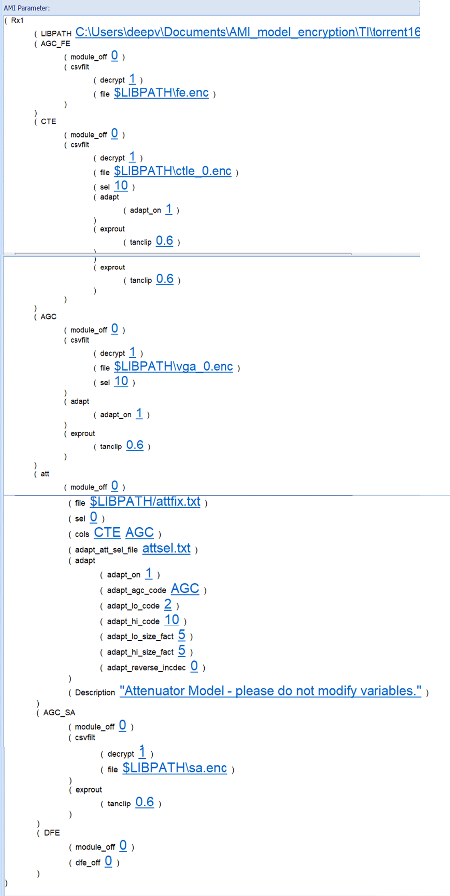
Table 2-7 provides a description of the Torrent16FFC Rx AMI parameters.
Note: If a parameter is not covered below, do
NOT adjust the values. Leave the default value!
Table 2-7 Description of the Torrent16FFC Rx
AMI Parameters
| Parameter | Description |
|---|---|
| AGC_FE |
|
| CTE file name |
|
| CTE options |
|
| AGC file name |
|
|
|
| AGC options | Variable Gain Amplifier
|
| Attenuator | Attenuation is adjusted by changing the number at the end of the CTLE
and/or the VGA file name. Use the following decode for increasing the
attenuation. Always increase the attenuation sequentially.
|
| AGC_SA |
|