SLVAF90 October 2021 TPS63805
2 TPS63805 Features
TPS63805 is a high-efficient non-inverting buck-boost converter. The input voltage can be higher or lower than output voltage. TPS63805 meets the requirements listed above, as shown in Table 2-1. Therefore, TPS63805 is a good option for the voltage stabilizer application.
| Part number | Input range | Output range | Package Group | Iq (Typ) | Iout (Max) |
|---|---|---|---|---|---|
| TPS63805 | 1.3 V-5.5 V | 1.8 V-5.2 V | DSBGA|15 (2.3mm×1.4mm) | DSBGA|15 (2.3mm×1.4mm) | 2 A |
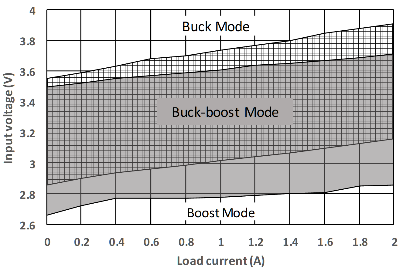
To regulate the output voltage VOUT when input voltage VIN is higher, lower or equal, the TPS63805 has three operation mode as shown in Figure 2-1. The figure also shows a hysteresis (non-overlapping area) among mode transitions in TPS63805. For certain load, when the converter enters buck-boost mode no matter from buck mode or boost mode, it would exit until the converter gets over the hysteresis area. Taking the 1 A load current as an example, the converter will enter buck-boost mode from boost mode when input voltage increases to 3.02 V but exit buck-boost mode until input voltage reduces to 2.78 V. The hysteresis not only expands the buck-boost mode area but also avoid a frequent mode transitions on the boundaries, this feature greatly benefit the voltage accuracy and ripple performance for voltage stabilizer.
 Figure 2-1 Mode Transition Thresholds of TPS63805
at Vout=3.3V
Figure 2-1 Mode Transition Thresholds of TPS63805
at Vout=3.3VThere are also two operating modes for TPS63805, which can be selected by MODE pin.
- Auto power save mode and PWM mode. The efficiency at light loading condition is high in this mode but the output voltage ripple will be large;
- Forced PWM mode. The efficiency is low at light loading condition in this mode but the output voltage ripple will be small.
Due to low output voltage ripple required in optical modules, forced PWM mode must be chosen when using TPS63805 as a voltage stabilizer. Figure 2-2 shows measured output voltage ripple on TPS63805EVM-026 with default setting. Though the ripple is smaller in forced PWM mode, it is still up to 20mV. The 10mV ripple requirement is not achieved.
To minimize output ripple, simply increase output capacitance is useful but it will bring much larger total solution size. Adding a low-pass inductor-capacitor (LC) filter on the output side can attenuate ripple effectively.