SBOA001A January 2000 – June 2020 INA117
3 Optional CMRR Adjustment
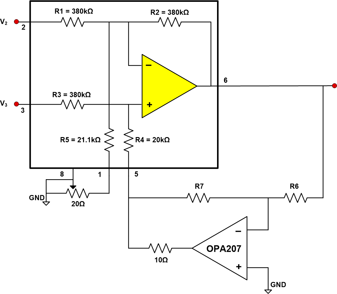
If CMRR adjustment is desired, add a 10Ω fixed resistor and a 20Ω pot as shown in Figure 4. Adjust CMRR by shorting together pins 2 and 3 of the INA117 (or INA149) and driving them with a 500Hz square wave while observing the output on a scope. Using a square wave rather than a sine wave allows the AC signal to settle out so that the DC CMRR can be seen. The CMRR trim will change the gain slightly, so trim CMRR first, then trim gain with R6, R7 if desired.
 Figure 4. INA117 with Increased Differential Input Range with CMRR Trim