SBOA001A January 2000 – June 2020 INA117
2 Device Overview
The performance of the INA117 depends on extremely precise resistor matching (0.005% for 86dB CMRR). These resistors are ratiometrically matched where resistor pairs must match to 0.005%. Absolute resistor values may vary up to ±15% based on process, but their matching is preserved. Resistors added to the input must be adjusted to at least this accuracy to maintain high performance. Both gain error and CMRR must be adjusted. Maintaining 86dB CMRR over temperature requires 1ppm/°C resistor TCR tracking. Significant resistance added external to the INA117 would require the same performance.
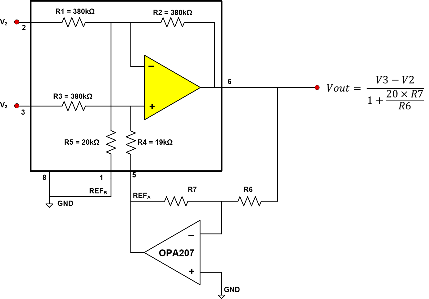
By using the circuit shown in Figure 1, internal resistor matching is preserved (with absolute values varying up to ±15%), and the INA117 CMRR and CMRR drift with temperature are maintained. Gain can be set independently of CMRR by adjusting the inverter resistors, R6, R7. Gain drift is preserved so long as R6 and R7 track with temperature. Furthermore, noise at the output is improved by the gain reduction factor whereas it is unchanged with the other approach.
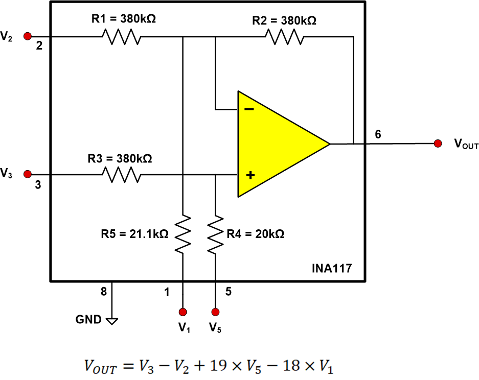
To understand how the circuit works, consider the INA117 to be a four-input summing amplifier as shown in Figure 2.
 Figure 2. INA117 Shown as a Four-Input Summing Amplifier
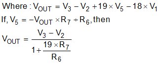
 CMRR is preserved and the gain is reduced if a small portion of the output signal is inverted and fed back to pin 5 with V1 set to zero (V1 grounded). Since absolute values of the internal resistors can vary up to ±15%, the following output equation may also exhibit the same level of error. This should be added to the overall system error budget.

Table 1. INA117 Selected-Gain Examples
| GAIN (1) (V/V) | R7 (kΩ) | R6 (kΩ) |
|---|---|---|
| 1/2 | 1.95 | 20.0 |
| 1/4 | 3.16 | 20.0 |
| 1/5 | 4.22 | 20.0 |
Similarly, the INA149 may be used. The INA149 is a precision 36V unity-gain difference amplifier with a very high input common-mode voltage range (±275V). It consists of a precision op amp and an integrated thin-film resistor network. The absolute value of these resistors are also ratiometrically matched with up to 15% variance in either direction. The INA149 is pin-compatible with the INA117 and offers improved DC performance.
 Figure 3. INA149 with Increased Differential Input Range
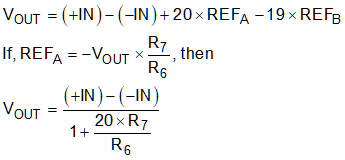
 The INA149 has the following transfer function:
Remember that the resistor values internal to the INA149 may also vary up to ±15% based on process, this error must be added to the overall system error budget. The output equation for increasing the differential input voltage is expressed below. This is derived from the transfer function:

Table 2. INA149 Selected-Gain Examples
| Gain (V/V)(1) | R7 (kΩ) | R6 (kΩ) |
| 1/2 | 1 | 20 |
| 2/3 | 0.5 | 20 |
| 3/4 | 0.33 | 20 |