SBAU279 October 2020 ADS7038-Q1
- Trademarks
- 1Introduction
- 2ADS7038Q1EVM-PDK Overview
- 3ADS7038Q1EVM-PDK Initial Setup
- 4Input Signal-Conditioning Circuitry on the ADS7038Q1EVM
- 5Bill of Materials, Printed Circuit Board Layout, and Schematics
3.3.5 Register Map
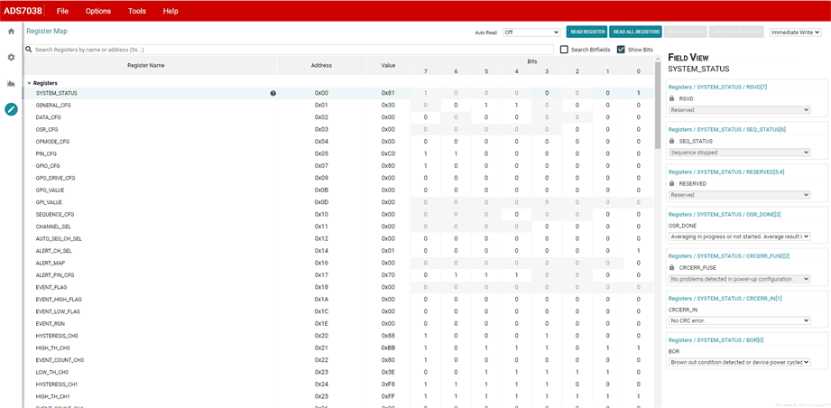
Figure 3-17 shows the register map for the ADS7038 device. On the top right corner are options to read registers individually or read all the registers, or write an individual register. Users can choose to have the register values modified in the GUI to be written on the device instantaneously by selecting the Immediate Write option or later using the Deferred Write drop-down option. In the field view, the registers are broken down into the configurable bits it controls. When making changes in the Field View, the bit being changed is highlighted in yellow in the register map.
The register settings can also be saved in an external file to be loaded back into the GUI through the File → Save Registers menu selection. This allows for different setting configurations to be saved and easily implemented into the GUI by loading it back through the File → Load Registers menu item.
The register configurations can also be saved as a comma-separated values (CSV) file containing the register address and content as configured in the GUI. This allows the user to configure the device easily through the GUI as desired, and then export the respective register addresses and content to reference when creating firmware.
 Figure 3-17 Register Map.