ZHCSGE1A July   2017  – August 2017 TPSM84203 , TPSM84205 , TPSM84212

PRODUCTION DATA.  

  1. 特性
  2. 应用
  3. 说明
    1.     Device Images
      1.      简化应用
  4. 修订历史记录
  5. Pin Configuration and Functions
    1.     Pin Functions
  6. Specifications
    1. 6.1 Absolute Maximum Ratings
    2. 6.2 Recommended Operating Conditions
    3. 6.3 ESD Ratings
    4. 6.4 Thermal Information
    5. 6.5 Electrical Characteristics
    6. 6.6 Switching Characteristics
    7. 6.7 Typical Characteristics (VOUT = 3.3 V)
    8. 6.8 Typical Characteristics (VOUT = 5 V)
    9. 6.9 Typical Characteristics (VOUT = 12 V)
  7. Detailed Description
    1. 7.1 Overview
    2. 7.2 Functional Block Diagram
    3. 7.3 Feature Description
      1. 7.3.1 Input Capacitors
      2. 7.3.2 Output Capacitors
      3. 7.3.3 Drop-Out Voltage
      4. 7.3.4 Internal Soft-Start
      5. 7.3.5 Safe Startup into Pre-Biased Outputs
      6. 7.3.6 Over-Current Protection
      7. 7.3.7 Output Over-Voltage Protection
      8. 7.3.8 Thermal Shutdown
    4. 7.4 Device Functional Modes
      1. 7.4.1 Normal Operation
      2. 7.4.2 Eco-mode Operation
  8. Application and Implementation
    1. 8.1 Application Information
    2. 8.2 Typical Application
      1. 8.2.1 Design Requirements
      2. 8.2.2 Detailed Design Procedure
        1. 8.2.2.1 Custom Design With WEBENCH® Tools
        2. 8.2.2.2 Input and Output Capacitors
      3. 8.2.3 Application Curves
        1. 8.2.3.1 EMI
  9. Power Supply Recommendations
  10. 10Layout
    1. 10.1 Layout Guidelines
    2. 10.2 Layout Example
  11. 11器件和文档支持
    1. 11.1 器件支持
      1. 11.1.1 开发支持
        1. 11.1.1.1 使用 WEBENCH® 工具创建定制设计
    2. 11.2 相关链接
    3. 11.3 Receiving Notification of Documentation Updates
    4. 11.4 Community Resources
    5. 11.5 商标
    6. 11.6 静电放电警告
    7. 11.7 Glossary
  12. 12机械、封装和可订购信息

封装选项

机械数据 (封装 | 引脚)
散热焊盘机械数据 (封装 | 引脚)
订购信息

EMI

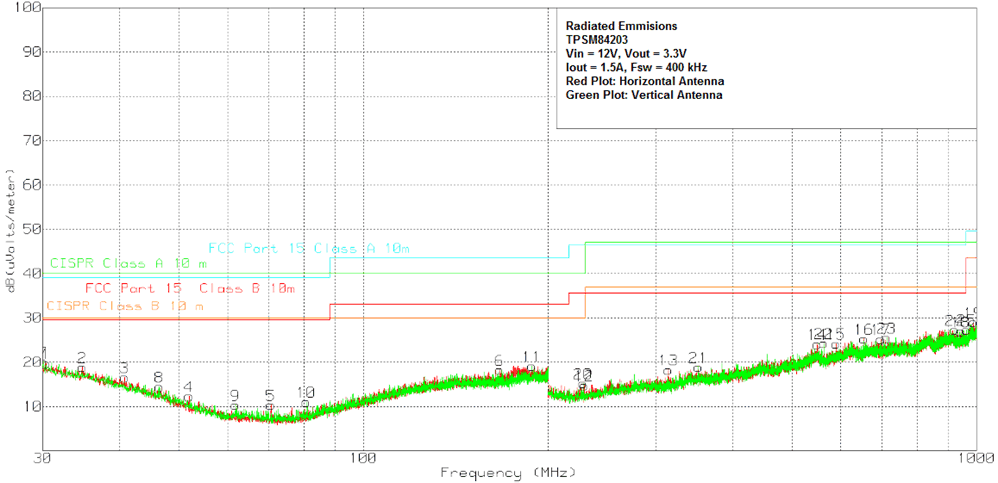
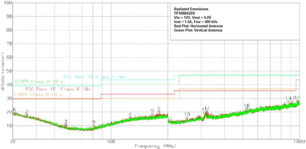
The TPSM842xx devices are all compliant with EN55022 Class B radiated emissions. Figure 23 to Figure 27 show typical examples of radiated emissions plots for the TPSM842xx devices. The EMI plots were taken using a web-orderable EVM with a resistive load. Input power was provided using a lead acid battery. All graphs show plots of the antenna in the horizontal and vertical positions.
TPSM84203 TPSM84205 TPSM84212 12Vin203EMI.gif
Figure 23. Radiated Emissions 12-V Input, 3.3-V Output,
1.5-A Load, Horizontal and Vertical Antenna
TPSM84203 TPSM84205 TPSM84212 12Vin205EMI.gif
Figure 24. Radiated Emissions 12-V Input, 5.0-V Output,
1.5-A Load, Horizontal and Vertical Antenna
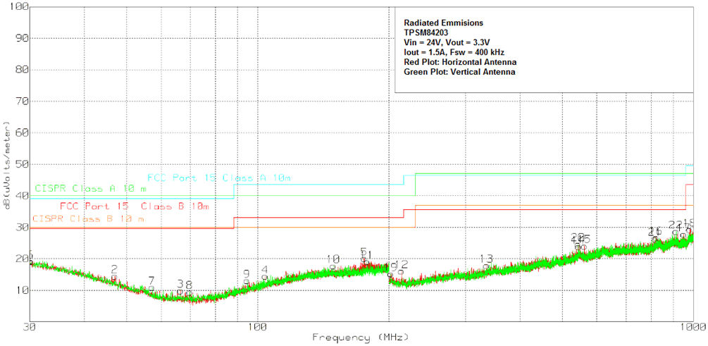
TPSM84203 TPSM84205 TPSM84212 24Vin203EMI.gifFigure 25. Radiated Emissions 24-V Input, 3.3-V Output,
1.5-A Load, Horizontal and Vertical Antenna
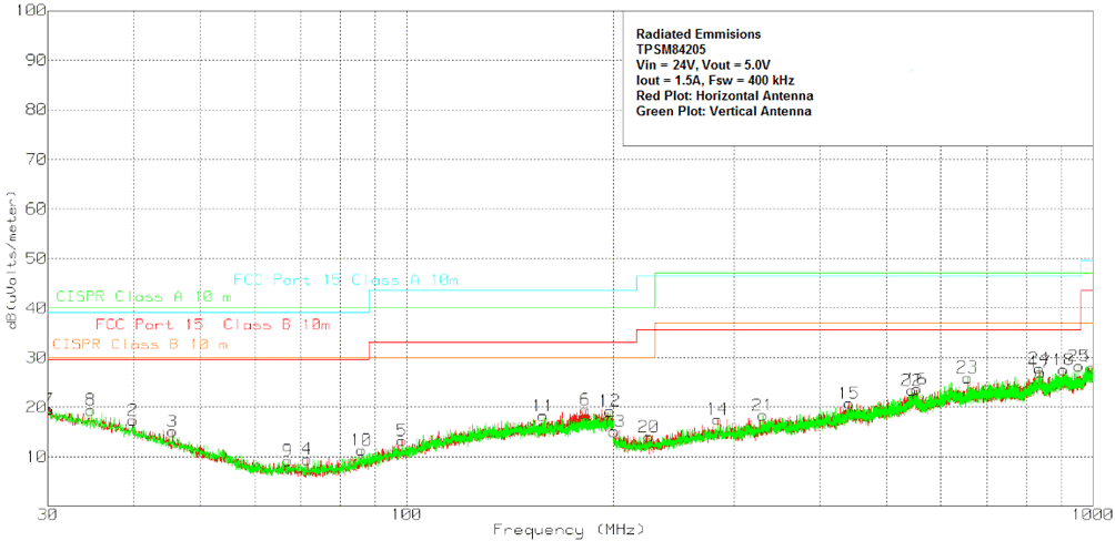
TPSM84203 TPSM84205 TPSM84212 24Vin205EMI.gifFigure 26. Radiated Emissions 12-V Input, 5.0-V Output,
1.5-A Load, Horizontal and Vertical Antenna
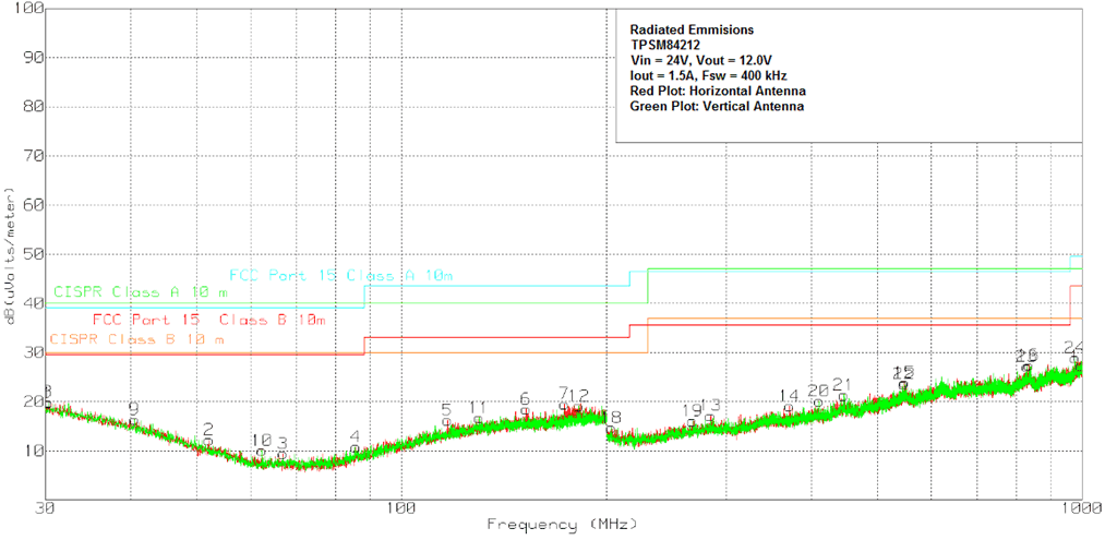
TPSM84203 TPSM84205 TPSM84212 24Vin212EMI.gifFigure 27. Radiated Emissions 24-V Input, 12-V Output,
1.5-A Load, Horizontal and Vertical Antenna