ZHCS845A March   2012  – July 2015 TPS2379

PRODUCTION DATA.  

  1. 特性
  2. 应用
  3. 说明
  4. 修订历史记录
  5. Pin Configuration and Functions
  6. Specifications
    1. 6.1 Absolute Maximum Ratings
    2. 6.2 ESD Ratings
    3. 6.3 Recommended Operating Conditions
    4. 6.4 Thermal Information
    5. 6.5 Electrical Characteristics
    6. 6.6 Typical Characteristics
  7. Parameter Measurement Information
  8. Detailed Description
    1. 8.1 Overview
    2. 8.2 Functional Block Diagram
    3. 8.3 Feature Description
      1. 8.3.1 CDB Converter Disable Bar Pin Interface
      2. 8.3.2 CLS Classification
      3. 8.3.3 DEN Detection and Enable
      4. 8.3.4 GATE Auxiliary Gate Driver
        1. 8.3.4.1 External Boost Circuit (Q1, Q2, and RBLST) Considerations
      5. 8.3.5 Internal Pass MOSFET
      6. 8.3.6 T2P Type-2 PSE Indicator
      7. 8.3.7 VDD Supply Voltage
      8. 8.3.8 VSS
      9. 8.3.9 PowerPAD
    4. 8.4 Device Functional Modes
      1. 8.4.1 PoE Overview
        1. 8.4.1.1  Threshold Voltages
        2. 8.4.1.2  PoE Start-Up Sequence
        3. 8.4.1.3  Detection
        4. 8.4.1.4  Hardware Classification
        5. 8.4.1.5  Inrush and Start-up
        6. 8.4.1.6  Maintain Power Signature
        7. 8.4.1.7  Start-up and Operation
        8. 8.4.1.8  PD Hotswap Operation
        9. 8.4.1.9  CDB and T2P
        10. 8.4.1.10 Auxiliary Pass MOSFET Control
        11. 8.4.1.11 Using DEN to Disable PoE
  9. Application and Implementation
    1. 9.1 Application Information
    2. 9.2 Typical Application
      1. 9.2.1 Design Requirements
      2. 9.2.2 Detailed Design Procedures
        1. 9.2.2.1 Input Bridges and Schottky Diodes
        2. 9.2.2.2 Protection, D1
        3. 9.2.2.3 Capacitor, C1
        4. 9.2.2.4 Detection Resistor, RDEN
        5. 9.2.2.5 Classification Resistor, RCLS
        6. 9.2.2.6 External Boost Circuit
      3. 9.2.3 Application Curves
  10. 10Power Supply Recommendations
  11. 11Layout
    1. 11.1 Layout Guidelines
      1. 11.1.1 EMI Containment
    2. 11.2 Layout Example
    3. 11.3 Thermal Considerations and OTSD
    4. 11.4 ESD
  12. 12器件和文档支持
    1. 12.1 文档支持
      1. 12.1.1 相关文档 
    2. 12.2 社区资源
    3. 12.3 商标
    4. 12.4 静电放电警告
    5. 12.5 Glossary
  13. 13机械、封装和可订购信息

封装选项

机械数据 (封装 | 引脚)
散热焊盘机械数据 (封装 | 引脚)
订购信息

特性

  • 带有状态标志的 IEEE 802.3at 2 类硬件分类
  • 辅助栅极驱动器,用于高功率扩展
  • 稳健耐用的 100V、0.5Ω 热插拔金属氧化物半导体场效应晶体管 (MOSFET)
  • 1A(典型值)工作电流限值
  • 140mA(典型值)浪涌电流限值
  • DC-DC 转换器使能
  • 15kV/8kV 系统级静电放电 (ESD) 功能
  • PowerPAD™HSOP 封装

应用

  • 符合 IEEE 802.3at 标准的器件
  • 通用以太网供电 (UPOE) 兼容器件
  • 视频和网络语音 (VoIP) 电话
  • 多频带访问点
  • 监控摄像机
  • 微微基站

说明

TPS2379器件是一款 8 引脚集成电路,包含 实现 IEEE802.3at 2 类受电设备 (PD) 所需的全部功能,例如检测、分类、2 类硬件分类以及启动时的 140 mA 浪涌电流限制。该控制器的内部开关电阻低至 0.5Ω,并且采用耐热增强型 PowerPAD 封装,因此能够长时间在高达 0.85A 的电流下运行。TPS2379 集成的内部开关电阻低至 0.5Ω,这使得 PD 能够在正常运行时长时间承受高达 0.85A 的电流。TPS2379 器件支持高功率 应用 ,但需要外接导通晶体管。TPS2379 包含多项保护 功能 ,例如热关断、折返电流限制以及稳健耐用的 100V 内部开关。

器件信息(1)

器件型号 封装 封装尺寸(标称值)
TPS2379 HSOP (8) 4.89mm × 3.90mm
  1. 要了解所有可用封装,请参见数据表末尾的可订购产品附录。

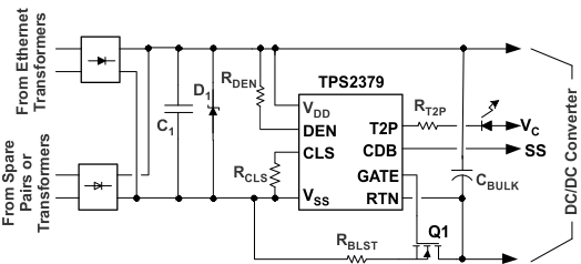
典型应用电路

TPS2379 typ_app_lvsb98.gif