ZHCSKV6C March 2020 – May 2024 TPA6211T-Q1
PRODUCTION DATA
- 1
- 1 特性
- 2 应用
- 3 说明
- 4 Pin Configuration and Functions
- 5 Specifications
- 6 Detailed Description
-
7 Application and Implementation
- 7.1 Application Information
- 7.2
Typical Applications
- 7.2.1
Typical Differential Input Application
- 7.2.1.1 Design Requirements
- 7.2.1.2 Detailed Design Procedure
- 7.2.1.3 Application Curves
- 7.2.2 Other Application Circuits
- 7.2.1
Typical Differential Input Application
- 7.3 Power Supply Recommendations
- 7.4 Layout
- 8 Device and Documentation Support
- 9 Revision History
- 10Mechanical, Packaging, and Orderable Information
7.2.1.2.4.3 Step 3: Additional Low-Pass Filter
Ra must be at least ten-times smaller than RI. Set Ra = 1 kΩ
Equation 29. 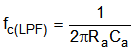
Therefore,
Equation 30. 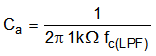
Substituting 10 kHz for fc(LPF) and solving for Ca:
Equation 31. Ca = 160 pF
Figure 7-3 is a bode plot for the band-pass filter in the previous example. Figure 7-8 shows how to configure the TPA6211T-Q1 device as a band-pass filter.
 Figure 7-3 Bode Plot