ZHCSE58C April   2012  – September 2015 LM3533

PRODUCTION DATA.  

  1. 特性
  2. 应用范围
  3. 说明
  4. 修订历史记录
  5. Pin Configuration and Functions
  6. Specifications
    1. 6.1 Absolute Maximum Ratings
    2. 6.2 ESD Ratings
    3. 6.3 Recommended Operating Conditions
    4. 6.4 Thermal Information
    5. 6.5 Electrical Characteristics
    6. 6.6 I2C Timing Requirements
    7. 6.7 Typical Characteristics
  7. Detailed Description
    1. 7.1 Overview
    2. 7.2 Functional Block Diagram
    3. 7.3 Feature Description
      1. 7.3.1 Control Bank Mapping
        1. 7.3.1.1 High-Voltage Control Banks (A/B)
        2. 7.3.1.2 Low-Voltage Control Banks (C, D, E, And F)
      2. 7.3.2 Pattern Generator
      3. 7.3.3 Ambient Light Sensor Interface
      4. 7.3.4 PWM Input
      5. 7.3.5 HWEN Input
      6. 7.3.6 Thermal Shutdown
    4. 7.4 Device Functional Modes
      1. 7.4.1  High-Voltage Boost Converter
        1. 7.4.1.1 High-Voltage Current Sinks (HVLED1 And HVLED2)
        2. 7.4.1.2 High-Voltage Current String Biasing
        3. 7.4.1.3 Boost Switching-Frequency Select
      2. 7.4.2  Integrated Charge Pump
        1. 7.4.2.1 Charge Pump Disabled
        2. 7.4.2.2 Automatic Gain
        3. 7.4.2.3 Automatic Gain (Flying Capacitor Detection)
        4. 7.4.2.4 1× Gain
        5. 7.4.2.5 2× Gain
        6. 7.4.2.6 Low-Voltage Current Sinks (LVLED1 to LVLED5)
        7. 7.4.2.7 Low-Voltage LED Biasing
      3. 7.4.3  LED Current Mapping Modes
        1. 7.4.3.1 Exponential Mapping
        2. 7.4.3.2 Linear Mapping
      4. 7.4.4  LED Current Ramping
        1. 7.4.4.1 Start-Up/Shutdown Ramp
        2. 7.4.4.2 Run-Time Ramp
      5. 7.4.5  Brightness Register Current Control
      6. 7.4.6  PWM Control
        1. 7.4.6.1 PWM Input Frequency Range
        2. 7.4.6.2 PWM Input Polarity
      7. 7.4.7  ALS Current Control
        1. 7.4.7.1 ALS Brightness Zones (Zone Boundaries)
        2. 7.4.7.2 Zone Boundary Hysteresis
        3. 7.4.7.3 Zone Target Registers (ALSM1, ALSM2, ALSM3)
        4. 7.4.7.4 PWM Input in ALS Mode
      8. 7.4.8  ALS Functional Blocks
        1. 7.4.8.1  ALS Input
        2. 7.4.8.2  Analog Output Ambient Light Sensors (ALS Gain Setting Resistors)
        3. 7.4.8.3  PWM Output Ambient Light Sensors (Internal Filtering)
        4. 7.4.8.4  Internal 8-Bit ADC
        5. 7.4.8.5  ALS Averager
        6. 7.4.8.6  Initializing the ALS
        7. 7.4.8.7  ALS Algorithms
        8. 7.4.8.8  ALS Rules
        9. 7.4.8.9  Direct ALS Control
        10. 7.4.8.10 Up-Only Control
        11. 7.4.8.11 Down-Delay Control
      9. 7.4.9  Pattern Generator
        1. 7.4.9.1 Delay Time
        2. 7.4.9.2 Rise Time
        3. 7.4.9.3 Fall Time
        4. 7.4.9.4 High Period
        5. 7.4.9.5 Low Period
        6. 7.4.9.6 Low-Level Brightness
        7. 7.4.9.7 High-Level Brightness
        8. 7.4.9.8 ALS Controlled Pattern Current
        9. 7.4.9.9 Interrupt Output Mode
      10. 7.4.10 Fault Flags/Protection Features
        1. 7.4.10.1 Open LED String (HVLED)
        2. 7.4.10.2 Shorted LED String (HVLED)
        3. 7.4.10.3 Open LED (LVLED)
        4. 7.4.10.4 Shorted LED (LVLED)
        5. 7.4.10.5 Overvoltage Protection (Inductive Boost)
        6. 7.4.10.6 Current Limit (Inductive Boost)
        7. 7.4.10.7 Current Limit (Charge Pump)
    5. 7.5 Programming
      1. 7.5.1 I2C-Compatible Interface
        1. 7.5.1.1 Start and Stop Conditions
        2. 7.5.1.2 I2C-Compatible Address
        3. 7.5.1.3 Transferring Data
    6. 7.6 Register Maps
      1. 7.6.1 LM3533 Register Descriptions
        1. 7.6.1.1 Pattern Generator Registers
  8. Application and Implementation
    1. 8.1 Application Information
    2. 8.2 Typical Application
      1. 8.2.1 Design Requirements
      2. 8.2.2 Detailed Design Procedure
        1. 8.2.2.1 Boost Converter Maximum Output Power (Boost)
        2. 8.2.2.2 Peak Current Limited
        3. 8.2.2.3 Output Voltage Limited
        4. 8.2.2.4 Maximum Output Power (Charge Pump)
      3. 8.2.3 Application Curves
  9. Power Supply Recommendations
  10. 10Layout
    1. 10.1 Layout Guidelines
      1. 10.1.1 Boost
        1. 10.1.1.1 Boost Output Capacitor Selection and Placement
        2. 10.1.1.2 Schottky Diode Placement
        3. 10.1.1.3 Inductor Placement
        4. 10.1.1.4 Boost Input Capacitor Selection and Placement
      2. 10.1.2 Charge Pump
        1. 10.1.2.1 Flying Capacitor (CP)
        2. 10.1.2.2 Output Capacitor (CPOUT)
        3. 10.1.2.3 Charge Pump Input Capacitor Placement
    2. 10.2 Layout Example
  11. 11器件和文档支持
    1. 11.1 器件支持
      1. 11.1.1 Third-Party Products Disclaimer
    2. 11.2 相关文档 
    3. 11.3 社区资源
    4. 11.4 商标
    5. 11.5 静电放电警告
    6. 11.6 Glossary
  12. 12机械、封装和可订购信息

封装选项

机械数据 (封装 | 引脚)
散热焊盘机械数据 (封装 | 引脚)
订购信息

1 特性

  • 驱动两个并联高电压发光二极管 (LED) 灯串为显示屏和键盘提供照明
  • 能够支持高达 40V 输出电压的高压灯串,并且效率高达 90%
  • 每灌电流高达 30mA(背光和指示灯)
  • 采用 8 位可编程背光代码实现 14 位指数调光
  • 可选择带有 128 个可编程增益设置电阻的模拟环境光传感器 (ALS) 输入或者带有内部低通滤波器的脉宽调制 (PWM) ALS 输入
  • 针对内容可调亮度控制的 PWM 输入
  • 五个用于指示器 LED 的低压电流阱
  • 用于提高效率和 VIN 工作范围的集成电荷泵
  • 内部图案生成引擎
  • 完全可编程 LED 分组和控制
  • 4 个可配置过压保护阈值(16V,24V,32V 和 40V)
  • 500kHz 和 1MHz 可编程开关频率
  • 27mm2 总体解决方案尺寸

2 应用范围

  • 用于智能手机照明的电源
  • 显示器、键区和指示器照明
  • RGB 指示器驱动器

3 说明

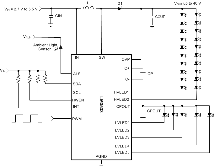
LM3533 是一款用于智能手机内背光、键盘和指示器 LED 的完整电源。 高压电感升压转换器为用于显示屏背光和键盘功能的两个串联 LED 灯串供电(HVLED1 和 HVLED2)。 集成电荷泵为五个低电压指示器 LED 电流阱(LVLED1 至 LVLED5)提供偏置。 所有低压电流阱均具有一种可编程图案生成器,可针对各种闪烁图案对其输出电流进行调制。

附加功能包括用于内容可调背光控制 (CABC) 的脉宽调制 (PWM) 控制输入以及一个带有 8 位内部模数转换器 (ADC) 的环境光传感器 (ALS) 接口,这两种功能可根据环境光照条件自动调节电流。 PWM 和 ALS 输入均可用于控制任何高电压或低电压电流阱。

LM3533 完全可由一个 I2C 兼容接口进行编程。 该器件采用
20 引脚芯片尺寸球状引脚栅格阵列 (DSBGA) 封装,其工作输入电压范围为 2.7V 至 5.5V,工作温度范围为 -40°C 至 +85°C。

器件信息(1)

部件号 封装 封装尺寸(最大值)
LM3533 DSBGA (20) 2.04mm x 1.78mm
  1. 要了解所有可用封装,请见数据表末尾的可订购产品附录。

典型应用电路

LM3533 30135701.gif