ZHCS091D February   2011  – March 2021 DRV8801-Q1

PRODUCTION DATA  

  1. 特性
  2. 应用
  3. 说明
  4. Revision History
  5. Pin Configuration and Functions
  6. Specifications
    1. 6.1 Absolute Maximum Ratings
    2. 6.2 ESD Ratings
    3. 6.3 Recommended Operating Conditions
    4. 6.4 Thermal Information
    5. 6.5 Electrical Characteristics
    6. 6.6 Timing Requirements
    7. 6.7 Typical Characteristics
  7. Detailed Description
    1. 7.1 Overview
    2. 7.2 Functional Block Diagram
    3. 7.3 Feature Description
      1. 7.3.1 Power Supervisor
      2. 7.3.2 Bridge Control
        1. 7.3.2.1 MODE 1
        2. 7.3.2.2 MODE 2
      3. 7.3.3 Fast Decay with Synchronous Rectification
      4. 7.3.4 Slow Decay with Synchronous Rectification (Brake Mode)
      5. 7.3.5 Charge Pump
      6. 7.3.6 SENSE
      7. 7.3.7 VPROPI
        1. 7.3.7.1 Connecting VPROPI Output to ADC
      8. 7.3.8 Protection Circuits
        1. 7.3.8.1 VBB Undervoltage Lockout (UVLO)
        2. 7.3.8.2 Overcurrent Protection (OCP)
        3. 7.3.8.3 Overtemperature Warning (OTW)
        4. 7.3.8.4 Overtemperature Shutdown (OTS)
      9. 7.3.9 Thermal Shutdown (TSD)
    4. 7.4 Device Functional Modes
  8. Application and Implementation
    1. 8.1 Application Information
    2. 8.2 Typical Application
      1. 8.2.1 Design Requirements
      2. 8.2.2 Detailed Design Procedure
        1. 8.2.2.1 Motor Voltage
        2. 8.2.2.2 Power Dissipation
        3. 8.2.2.3 Thermal Considerations
          1. 8.2.2.3.1 Junction-to-Ambiant Thermal Impedance (ƟJA)
        4. 8.2.2.4 Motor Current Trip Point
        5. 8.2.2.5 Sense Resistor Selection
        6. 8.2.2.6 Drive Current
      3. 8.2.3 Pulse-Width Modulating
        1. 8.2.3.1 Pulse-Width Modulating ENABLE
        2. 8.2.3.2 Pulse-Width Modulating PHASE
      4. 8.2.4 Application Curves
    3. 8.3 Parallel Configuration
      1. 8.3.1 Parallel Connections
      2. 8.3.2 Non – Parallel Connections
      3. 8.3.3 Wiring nFAULT as Wired OR
      4. 8.3.4 Electrical Considerations
        1. 8.3.4.1 Device Spacing
        2. 8.3.4.2 Recirculation Current Handling
        3. 8.3.4.3 Sense Resistor Selection
        4. 8.3.4.4 Maximum System Current
  9. Power Supply Recommendations
    1. 9.1 Bulk Capacitance
  10. 10Layout
    1. 10.1 Layout Guidelines
    2. 10.2 Layout Example
  11. 11Device and Documentation Support
    1. 11.1 Documentation Support
      1. 11.1.1 Related Documentation
    2. 11.2 Receiving Notification of Documentation Updates
    3. 11.3 支持资源
    4. 11.4 Trademarks
    5. 11.5 静电放电警告
    6. 11.6 术语表
  12. 12Mechanical, Packaging, and Orderable Information

封装选项

机械数据 (封装 | 引脚)
散热焊盘机械数据 (封装 | 引脚)
订购信息

说明

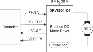
DRV8801-Q1 包含全 H 桥驱动器,提供多用途电源驱动器解决方案。此器件能够驱动一个有刷直流电机或者步进电机的一个绕组,以及其它诸如螺线管等器件。通过一个简单的相位/使能接口即可轻松与控制器电路相连

输出级使用配置为 ½H 桥的 N 通道功率 MOSFET。DRV8801-Q1 能够提供高达 ±2.8A 的峰值输出电流和高达 38V 的工作电压。一个内部电荷泵可用来生成所需的栅极驱动电压。

低功耗睡眠模式可将部分内部电路关断,以实现极低的静态电流和功耗。可使用一个专用的 nSLEEP 引脚来设定这个睡眠模式。

提供的内部保护功能包括:欠压锁定、过流保护、电源短路保护、接地短路保护、过热警告和过热关断。过流(包括接地短路和电源短路)和过热故障条件由 nFAULT 引脚指示。

DRV8801-Q1 采用 16 引脚 QFN 封装,具有外露散热焊盘,可以更好地散热。

器件信息
器件型号(1) 封装 封装尺寸(标称值)
DRV8801-Q1 QFN (16) 4.00mm x 4.00mm
如需了解所有可用封装,请参阅数据表末尾的可订购产品附录。
GUID-EA5E76B7-D2F9-475F-86F0-741D2252E581-low.gif简化版原理图