| STATIC CHARACTERISTICS |
| BVDSS |
Drain-to-source voltage |
VGS = 0 V, ID = 250 μA |
100 |
|
|
V |
| IDSS |
Drain-to-source leakage current |
VGS = 0 V, VDS = 80 V |
|
|
1 |
μA |
| IGSS |
Gate-to-source leakage current |
VDS = 0 V, VGS = 20 V |
|
|
100 |
nA |
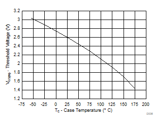
| VGS(th) |
Gate-to-source threshold voltage |
VDS = VGS, ID = 250 μA |
2.2 |
2.6 |
3.2 |
V |
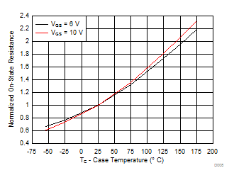
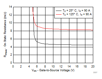
| RDS(on) |
Drain-to-source on resistance |
VGS = 6 V, ID = 90 A |
|
5.3 |
6.6 |
mΩ |
| VGS = 10 V, ID = 90 A |
|
4.6 |
5.6 |
mΩ |
| gfs |
Transconductance |
VDS = 10 V, ID = 90 A |
|
113 |
|
S |
| DYNAMIC CHARACTERISTICS |
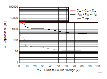
| Ciss |
Input capacitance |
VGS = 0 V, VDS = 50 V, ƒ = 1 MHz |
|
3890 |
5060 |
pF |
| Coss |
Output capacitance |
|
674 |
876 |
pF |
| Crss |
Reverse transfer capacitance |
|
14 |
18 |
pF |
| RG |
Series gate resistance |
|
|
1.3 |
2.6 |
Ω |
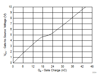
| Qg |
Gate charge total (10 V) |
VDS = 50 V, ID = 90 A |
|
44 |
57 |
nC |
| Qgd |
Gate charge gate to drain |
|
5.6 |
|
nC |
| Qgs |
Gate charge gate to source |
|
17 |
|
nC |
| Qg(th) |
Gate charge at Vth |
|
9.6 |
|
nC |
| Qoss |
Output charge |
VDS = 50 V, VGS = 0 V |
|
124 |
|
nC |
| td(on) |
Turn on delay time |
VDS = 50 V, VGS = 10 V,
IDS = 90 A, RG = 0 Ω |
|
9 |
|
ns |
| tr |
Rise time |
|
3 |
|
ns |
| td(off) |
Turn off delay time |
|
14 |
|
ns |
| tf |
Fall time |
|
2 |
|
ns |
| DIODE CHARACTERISTICS |
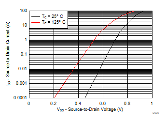
| VSD |
Diode forward voltage |
ISD = 90 A, VGS = 0 V |
|
0.9 |
1.0 |
V |
| Qrr |
Reverse recovery charge |
VDS= 50 V, IF = 90 A,
di/dt = 300 A/μs |
|
326 |
|
nC |
| trr |
Reverse recovery time |
|
74 |
|
ns |
