-
DACx1001 20 位、18 位和 16 位的低噪声、超低谐波失真、快速趋稳、高电压输出数模转换器 (DAC)
- 1 特性
- 2 应用
- 3 说明
- 4 修订历史记录
- 5 Device Comparison Table
- 6 Pin Configuration and Functions
-
7 Specifications
- 7.1 Absolute Maximum Ratings
- 7.2 ESD Ratings
- 7.3 Recommended Operating Conditions
- 7.4 Thermal Information Package
- 7.5 Electrical Characteristics
- Table 1. Timing Requirements: Write, 4.5 V ≤ DVDD ≤ 5.5 V
- Table 2. Timing Requirements: Write, 2.7 V ≤ DVDD < 4.5 V
- Table 3. Timing Requirements: Read and Daisy-Chain Write, 4.5 V ≤ DVDD ≤ 5.5 V
- Table 4. Timing Requirements: Read and Daisy-Chain Write, 2.7 V ≤ DVDD < 4.5 V
- 7.6 Typical Characteristics
-
8 Detailed Description
- 8.1 Overview
- 8.2 Functional Block Diagram
- 8.3 Feature Description
- 8.4 Device Functional Modes
- 8.5 Programming
- 8.6
Register Map
- 8.6.1 NOP Register (address = 00h) [reset = 0x000000h]
- 8.6.2 DAC-DATA Register (address = 01h) [reset = 0x000000h]
- 8.6.3 CONFIG1 Register (address = 02h) [reset = 004C80h for bits [23:0]]
- 8.6.4 DAC-CLEAR-DATA Register (address = 03h) [reset = 000000h for bits [23:0]]
- 8.6.5 TRIGGER Register (address = 04h) [reset = 000000h for bits [23:0]]
- 8.6.6 STATUS Register (address = 05h) [reset = 000000h for bits [23:0]]
- 8.6.7 CONFIG2 Register (address = 06h) [reset = 000040h for bits [23:0]]
- 9 Application and Implementation
- 10Power Supply Recommendations
- 11Layout
- 12器件和文档支持
- 13机械、封装和可订购信息
- 重要声明
DATA SHEET
DACx1001 20 位、18 位和 16 位的低噪声、超低谐波失真、快速趋稳、高电压输出数模转换器 (DAC)
本资源的原文使用英文撰写。 为方便起见,TI 提供了译文;由于翻译过程中可能使用了自动化工具,TI 不保证译文的准确性。 为确认准确性,请务必访问 ti.com 参考最新的英文版本(控制文档)。
1 特性
- 20 位单调性:1-LSB DNL(最大值)
- 积分线性:4-LSB INL(最大值)
- 低噪声:7nV/√Hz
- 独立于代码的低干扰:
1nV-s - 出色的 THD:1kHz fOUT 时为 -105 dB
- 快速趋稳:1µs
- 灵活的输出范围:VREFPF 至 VREFNF
- 集成式精密反馈电阻器
- 50MHz、4 线 SPI 兼容接口
- 读回
- 菊花链
- 温度范围:-40°C 至 +125°C
- 封装:48 引脚 TQFP
3 说明
20 位 DAC11001A、18 位 DAC91001 和 16 位 DAC81001 (DACx1001) 是高精度、低噪声、电压输出、单通道数模转换器 (DAC)。DACx1001 根据设计具有单调性,可以在所有范围内提供低于 4LSB(最大值)的出色线性度。
非缓冲电压输出可提供低噪声性能 (7nV/√Hz) 和快速稳定时间 (1µs),因此这款器件非常适合低噪声、快速控制环路和波形生成 应用中的数字输入 D 类音频放大器。DACx1001 兼具增强型抗尖峰脉冲电路以及独立于代码的超低干扰 (1nV-s),可实现干净的波形斜升和超低总谐波失真 (THD)。
DACx1001 器件包含上电复位电路,因此 DAC 能够使用寄存器中的已知值供电。使用外部基准,可以实现 VREFPF 到 VREFNF 的 DAC 输出,包括非对称输出范围。
DACx1001 使用一个在高达 50MHz 的时钟频率下运行的通用 4 线串行接口。DACx1001 的额定工业工作温度范围为 -40°C 至 +125°C。
器件信息(1)
| 器件型号 | 封装 | 封装尺寸(标称值) |
|---|---|---|
| DAC11001 | TQFP (48) | 7.00mm × 7.00mm |
| DAC91001(预发布) | ||
| DAC81001(预发布) |
- 如需了解所有可用封装,请参阅数据表末尾的封装选项附录。
Device Images
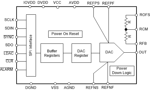
功能方框图

高精度控制环路电路

4 修订历史记录
Changes from * Revision (October 2019) to A Revision
- Changed 将 DAC11001A 器件从“预告信息(预发布)”更改为“生产数据(正在供货)”Go