-
DRV2605 用于具有内置库和智能环路架构的 ERM 和 LRA 触觉驱动器
- 1 特性
- 2 应用
- 3 说明
- 4 修订历史记录
- 5 Pin Configuration and Functions
- 6 Specifications
-
7 Detailed Description
- 7.1 Overview
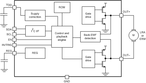
- 7.2 Functional Block Diagram
- 7.3
Feature Description
- 7.3.1 Support for ERM and LRA Actuators
- 7.3.2 Smart-Loop Architecture
- 7.3.3 Open-Loop Operation for LRA
- 7.3.4 Open-Loop Operation for ERM
- 7.3.5 Flexible Front-End Interface
- 7.3.6 Edge Rate Control
- 7.3.7 Constant Vibration Strength
- 7.3.8 Battery Voltage Reporting
- 7.3.9 One-Time Programmable (OTP) Memory for Configuration
- 7.3.10 Low-Power Standby
- 7.3.11 Device Protection
- 7.4 Device Functional Modes
- 7.5
Programming
- 7.5.1 Auto-Resonance Engine Programming for the LRA
- 7.5.2 Automatic-Level Calibration Programming
- 7.5.3 I2C Interface
- 7.5.4 Programming for Open-Loop Operation
- 7.5.5 Programming for Closed-Loop Operation
- 7.5.6 Auto Calibration Procedure
- 7.5.7 Programming On-Chip OTP Memory
- 7.5.8 Waveform Playback Programming
- 7.6
Register Map
- 7.6.1 Status (Address: 0x00)
- 7.6.2 Mode (Address: 0x01)
- 7.6.3 Real-Time Playback Input (Address: 0x02)
- 7.6.4 (Address: 0x03)
- 7.6.5 Waveform Sequencer (Address: 0x04 to 0x0B)
- 7.6.6 GO (Address: 0x0C)
- 7.6.7 Overdrive Time Offset (Address: 0x0D)
- 7.6.8 Sustain Time Offset, Positive (Address: 0x0E)
- 7.6.9 Sustain Time Offset, Negative (Address: 0x0F)
- 7.6.10 Brake Time Offset (Address: 0x10)
- 7.6.11 Audio-to-Vibe Control (Address: 0x11)
- 7.6.12 Audio-to-Vibe Minimum Input Level (Address: 0x12)
- 7.6.13 Audio-to-Vibe Maximum Input Level (Address: 0x13)
- 7.6.14 Audio-to-Vibe Minimum Output Drive (Address: 0x14)
- 7.6.15 Audio-to-Vibe Maximum Output Drive (Address: 0x15)
- 7.6.16 Rated Voltage (Address: 0x16)
- 7.6.17 Overdrive Clamp Voltage (Address: 0x17)
- 7.6.18 Auto-Calibration Compensation Result (Address: 0x18)
- 7.6.19 Auto-Calibration Back-EMF Result (Address: 0x19)
- 7.6.20 Feedback Control (Address: 0x1A)
- 7.6.21 Control1 (Address: 0x1B)
- 7.6.22 Control2 (Address: 0x1C)
- 7.6.23 Control3 (Address: 0x1D)
- 7.6.24 Control4 (Address: 0x1E)
- 7.6.25 V(BAT) Voltage Monitor (Address: 0x21)
- 7.6.26 LRA Resonance Period (Address: 0x22)
- 8 Application and Implementation
- 9 Power Supply Recommendations
- 10Layout
- 11器件和文档支持
- 12机械、封装和可订购信息
- 重要声明
DRV2605 用于具有内置库和智能环路架构的 ERM 和 LRA 触觉驱动器
1 特性
- 灵活触控反馈/Vibra 驱动程序
- LRA(线性谐振致动器)
- ERM(偏轴转动惯量)
- 由 I2C 控制的数字回放引擎
- 通过 I2C 实现的实时回放模式
- 智能环路架构(1)
- 自动过驱/制动 (ERM/LRA)
- 自动谐振跟踪 (LRA)
- 自动致动器诊断 (ERM/LRA)
- 自动水平校准 (ERM/LRA)
- 已获许可的 Immersion™TouchSense®2200 特性:
- 占空比控制范围介于 0% 至 100% 之间的可选脉宽调制 (PWM) 输入
- 可选模拟输入控制
- 可选硬件触发引脚
- 高效输出驱动
- 快速启动时间
- 电源电压上的持续加速
- 1.8V 兼容,VDD 容限数字引脚 (1)
2 应用
- 手机和平板电脑
- 手表和可穿戴技术
- 远程控制、鼠标和外设器件
- 支持触觉反馈的器件
- 人机界面
3 说明
DRV2605 器件设计用于通过共享的 I2C 兼容总线提供极为灵活的 ERM 和 LRA 传动器触控。该控制使得主机处理器不用再生成脉宽调制 (PWM) 驱动信号,从而节省了代价高昂的定时器中断和硬件引脚。
DRV2605 器件具有内容丰富的集成库,可提供来自 ERM 和 LRA Immersion 的 100 多种已获许可的效果,从而免除了对设计触控波形的需要。
DRV2605 器件可提供许可版本的 Immersion TouchSense 2200 软件,其中包括 2200 效果库和 2200 音频至气氛 功能。此外,主机处理器可利用实时回放模式绕过库回放引擎并通过 I2C 从主机直接播放波形。
DRV2605 器件还包含一个智能环路架构,此架构可轻松实现 LRA 自动谐振驱动以及优化反馈的 ERM 驱动。这种反馈提供了自动过驱和制动,从而生成了一个简化的输入波形图并实现了可靠的电机控制和稳定的电机性能。音频至触觉模式自动将音频输入信号转换为实际的触控效果。
DRV2605 器件 具有 一个经三重调制的输出级,从而能够提供比基于线性的输出驱动器更高的效率。DRV2605 器件采用 9 焊球 WCSP 封装,具有很少的组件数量,操作灵活,是支持触控的便携式振动和触觉 应用的理想选择。
有关 Immersion 软件的重要说明,请参阅 法律声明 部分。
器件信息(1)
| 器件型号 | 封装 | 封装尺寸(最大值) |
|---|---|---|
| DRV2605 | DSBGA (9) | 1.50mm x 1.50mm |
- 如需了解所有可用封装,请参阅数据表末尾的可订购产品附录。

4 修订历史记录
Changes from D Revision (December 2015) to E Revision
- Changed the DEFAULT value for bit 5-4 of Table 25 From: 1 To 3 Go
- Changed the DEFAULT value for bit 3-2 of Table 25 From: 2 To 1 Go
- Changed the DEFAULT value for bit 1-0 of Table 25 From: 2 To 1 Go
- Changed the typical value of C(VDD) in Table 30 From: 0.1 µF To: 1 µFGo
- Changed C(VDD) from 0.1 to 1 µF in Figure 56Go
- Changed the input-voltage supply range From: 2 V to 5.2 V To: 2.5 V to 5.5 V in the Power Supply Recommendations sectonGo
Changes from C Revision (September 2014) to D Revision
- Changed th(1) Hold time, SCL to SDA from 10 ns to 50 ns in Timing RequirementsGo
- Changed the default value of NG_THRESH[1:0] from 1 to 2 in the Register MapControl3 Register Field DescriptionsGo
Changes from B Revision (February 2014) to C Revision
- Changed 将特性 项目符号从免专利费集成 Immersion 库更改为波形事件序列生成器和触发器Go
- Changed 特性项目符号从音频至触觉模式更改为顶级:经许可的 Immersion TouchSense 2200 特性:Go
- Changed 从音频至触觉模式更改为音频至气氛Go
- Changed 更改了 说明 的第二段,用于澄清。Go
- Updated document to new datasheet styleGo
- Deleted Operating free-air temperature range, TA (information replaced by Thermal Information table) Go
- Changed EN pulldown resistance added to Electrical CharacteristicsGo
- Changed connection terminal of input impedance from GND to V(CM_ANA) in Electrical Characteristics sectionGo
- Moved switching parameters to new Switching Characteristics table Go
- Added TI Haptic Broadcast Mode sectionGo
- Changed AC couple capacitor recommendation from 0.1 µF to 1 µF to be consistent with Recommended External Components table.Go
- Added Immersion 法律声明 Go
Changes from A Revision (March 2013) to B Revision
- Changed 从一页数据表更改为产品文件夹中的全部数据表Go
Changes from * Revision (December 2012) to A Revision
- Changed minimum supported resonant frequency from 50 Hz to 125 Hz Go
- Added digital pulldown resistance parameter to Electrical CharacteristicsGo
- Changed |IIH| MAX value from 3 to 3.5µA per CMS #C1303020Go
- Changed calibration diagram to include DRIVE_TIME into ERM requirementsGo
- Changed bitfield name from "LRA_DRIVE_MODE" to "OTP_STATUS"Go
- Changed C(REG) from 0.1 to 1 µF in Figure 56Go