SLVAF60A May 2021 – October 2021 TPD1E01B04-Q1 , TPD4E02B04-Q1
1 Application Brief
Introduction
Automotive display or camera systems typically require serializers and deserializers (SerDes) for data transmission. When using automotive SerDes protocols, it is important to design for protection from ESD strikes to the IEC 61000-4-2 or ISO 10605 standards since these protocols have external connectors. When the cabling is connected to these external connectors, the built-up charge on the cables can possibly cause a high-voltage ESD strike. ESD strikes without adequate protection could lead to catastrophic system failures. ESD diodes are a very efficient and robust way of protecting the systems. In the event of an ESD strike, the ESD diode breaks down and creates a low impedance path that limits the peak voltage and current by diverting the current flow to ground, thereby protecting the ICs in the signal chain. However, to ensure adequate protection, it is important to understand how to properly select and place an ESD diode.
ESD Locations in Automotive SerDes
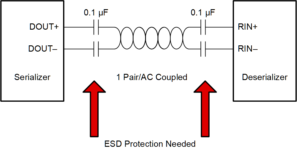
At a high level, automotive SerDes applications consist of 3 main sections: a serializer, a deserializer, and the cabling connecting the serializer and the deserializer. The cabling in the middle is where ESD events are most likely to occur. The cabling connects the DOUT pins on the serializer side to the RIN pins on the deserializer side. This cabling comes in different configurations; some of them could be: coax, twisted pair, or star quad. Along with the different types of cabling, the signaling comes in the form of single ended or differential.
 Figure 1-1 SerDes Block Diagram
Working Voltage Considerations
When using an ESD diode, do not allow the normal operating voltage levels across the line it is protecting to exceed the VRWM of the diode; otherwise, the diode will fail and short the signal to ground. In some automotive SerDes applications, there could be a DC bias across the bus that powers the downstream circuitry. For example, a serializer datasheet might state that the max bus voltage on the output pin is around 2 V, but in ADAS applications using power over coax (PoC), the DC bias can increase the common-mode voltage of the bus up to 9 V. One possible solution to this issue would be to select an ESD diode with a higher VRWM that can handle the additional DC bias. However, having a higher VRWM will result in a higher clamping voltage, which means the output pins of the serializer are more likely to be damaged during an ESD event.
Component Placement for Optimized Protection
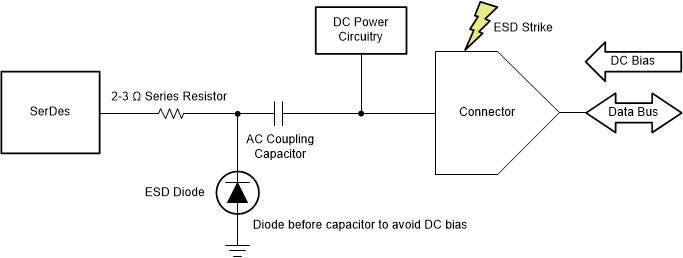
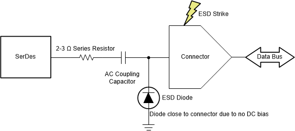
In automotive SerDes applications, there is an AC coupling capacitor at the end of each bus line, near the pins of the device. An alternative ESD solution for automotive SerDes applications with an additional DC bias, like PoC, is to place the diode on the SerDes side of the AC coupling cap. In this configuration, the capacitor will be able to filter out the DC bias and lower the voltage back down to normal levels. If there is no DC bias, place the diode as close to the external connector as possible.
One final aspect to consider is the internal ESD protection circuitry the SerDes devices have. According to the SEED method, the on-chip ESD cell and any external ESD protection, such as a diode, are combined together to give you the total system-level ESD robustness. However, with some automotive SerDes devices, the internal protection circuitry might start conducting before the external diode during an ESD event. This lowers the overall ESD rating of your system since the diode does not conduct. To ensure the diode conducts first during an ESD event and improves the ESD rating of your system, an isolating series resistor might be needed between the ESD source and the DUT pin. A typical value for an isolating resistance in these applications is about 2-3 Ohms. To determine whether or not an additional resistor is needed, check the pin & bond wire resistance of the SerDes device, the trace resistance on the board, and any other resistive components like common-mode chokes to determine if the total resistance between the diode and the IC equals the minimum required isolation value. Refer to Figure 1-2 and Figure 1-3 for more details.
 Figure 1-2 Powered Over Cable
 Figure 1-3 Non-powered Over Cable
Device Recommendations
Automotive SerDes applications require high signal speeds, so keeping the line capacitance of the ESD diodes very low is important to maintaining signal integrity. The diodes also must have good IEC-61000-4-2 ratings and low clamping voltages. TI offers two ESD devices that protect automotive SerDes applications and other high-speed applications such as USB 3.2 very well. TPD1E01B04-Q1 can support signals up to 20 Gbps, and TPD4E02B04-Q1 can support signals up to 10 Gbps. Refer to Table 1-1 for more details.
| TPD1E01B04-Q1 | TPD4E02B04-Q1 | |
|---|---|---|
| # of Channels | 1 | 4 |
| VRWM | 3.6 V | 3.6 V |
| Capacitance | 0.2 pF | 0.25 pF |
| IEC 61000-4-5 Contact Rating | 15 kV | 12 kV |
| Clamping Voltage at 1 A | 7 V | 6.6 V |
| Comments | Best for single line protection (ADAS) | Best for infotainment protection (blocks of 4 wires) |