SLLA527A September 2020 – February 2021 DRV8714-Q1 , DRV8718-Q1
Application Brief
Introduction
Simple user error can lead to unintentional damage to a vehicle if proper precautions are not taken. Engineers must design robust solutions that can work effectively in a variety of scenarios. An easy-to-overlook problem is properly handling the voltage surge that can be generated by manually opening, closing or adjusting any part of the vehicle that is connected to a motor.
If high enough, this voltage surge can cause damage to connected components. Engineers must therefore design a solution that can protect the system, either when the vehicle is powered on or even when it’s powered off. Examples of how this issue can occur in the first place will be discussed next.
Real World Scenarios
An example of when this problem can occur is during a family trip outdoors. The family may park their vehicle, turn it off and open up the powered lift gate. The lift gate may be kept open for an extended period of time while they retrieve items from the trunk, use the trunk as a sitting area or simply just forget about the lift gate. By design, when the vehicle is powered off the majority of its subsystems are also powered off or kept in a low-power mode to avoid draining the battery as much as possible.
It’s common for people to forget to use the lift gate’s close button and instead slam it shut manually. By doing so, the lift gate’s motors are unintentionally spun and can generate a voltage surge that the system must protect against or risk potential damage. Other scenarios where this problem can pop up include when an individual manually closes an automatic sliding door, a thief pries open a trunk or a worker on an assembly line adjusts a motorized seat to put it in place. Understanding how this issue can occur is a good first step, but it is equally important to understand why this is a problem.
 Figure 1-1 Example scenarios where a
motor may be externally driven
Figure 1-1 Example scenarios where a
motor may be externally drivenUnderstanding the Problem
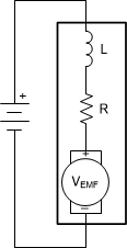
A brushed DC motor works by using the applied voltage to generate a current that flows through the armature. The current flowing through the winding within the armature generates a magnetic field. This magnetic field pushes away from the internal permanent magnets in the motor which then results in the rotation of the motor’s shaft. As the motor rotates, an opposing voltage is generated by the magnetic field and is referred to as back electromotive force (back EMF). The back EMF voltage scales based on the motor’s angular velocity but does not exceed the motor’s applied voltage in normal conditions.
 Figure 1-2 Simplified System Motor
Model
Figure 1-2 Simplified System Motor
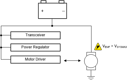
ModelHowever, if the motor is assisted by an external force then this supplemental force can result in the motor’s back EMF exceeding the supply voltage and sending voltage back into the system. If this voltage surge exceeds any connected component’s absolute maximum voltage rating, this can result in component damage and failure.
 Figure 1-3 This illustration shows how
back EMF voltage surge can damage connected components
Figure 1-3 This illustration shows how
back EMF voltage surge can damage connected componentsExternal and Integrated Solution
One approach to prevent this issue is to use the motor driver’s braking mode. This mode disables the H-bridge’s high-side MOSFETs while enabling the low-side MOSFETs. This prevents the back EMF voltage spike from flowing back into the analog power rail, while allowing the back EMF to safely dissipate.
 Figure 1-4 Current flow and voltage path when the motor is in slow decay mode
Activating the motor driver’s braking mode is easier when the system is fully powered on. On a powered off system, engineers need to limit the system’s power consumption to avoid rapidly draining the vehicle’s battery. To accomplish this most components on the system are powered off or left in a low power mode. In some cases, a system may not have power at all if the battery has been completely drained or has been physically disconnected from the vehicle.
An external solution that can protect the system in all three scenarios typically requires some sort of tradeoff. Engineers must balance the solution’s robustness, size, cost and overall power consumption. By using a motor driver with integrated protection, engineers can avoid having to make these tradeoffs. One option would be Texas Instruments’ DRV8718-Q1 and DRV8714-Q1 gate drivers that provides a robust, cost effective and low power integrated solution.
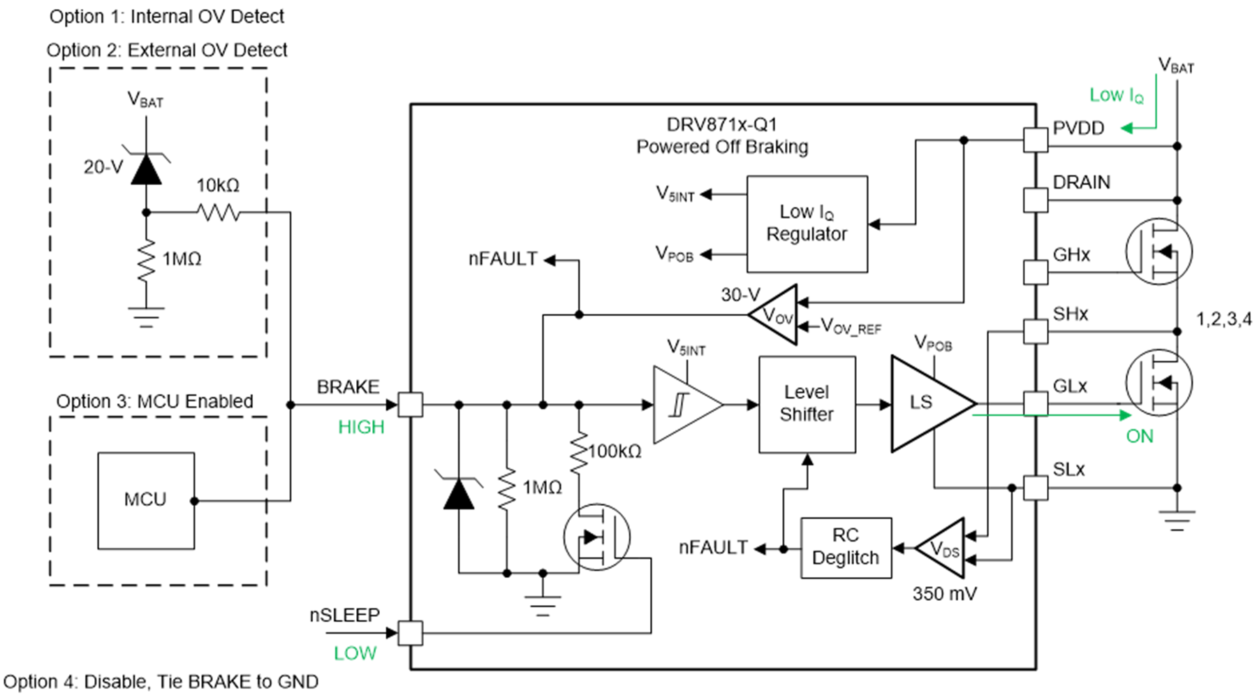
At a high level DRV8718-Q1 and DRV8714-Q1, which are eight and four channel half-bridge gate drivers, integrate an internal regulator with an ultra-low sleep current. The regulator powers up a minimal portion of the device while keeping the rest of the device in a low power mode. This provides a low power way for the gate driver to constantly monitor the voltage level of the analog power rail.
If the analog power rail exceeds a voltage threshold the gate driver will automatically go into brake mode thus allowing the back EMF to safely dissipate while protecting the rest of the system. This feature is called powered off braking. An external BRAKE pin on the device provides additional flexibility for system designers. This pin can be used to enable or disable powered off braking or to change the voltage trigger threshold.
 Figure 1-5 Block diagram of the powered
off braking subsystem within DRV8718-Q1 and DRV8714-Q1
Figure 1-5 Block diagram of the powered
off braking subsystem within DRV8718-Q1 and DRV8714-Q1Conclusion
To summarize, the back EMF voltage surge from an externally driven motor is a significant problem that engineers need to take care of to avoid system wide issues. An external solution not only adds complexity but also cost.
By using Texas Instruments’ DRV8718-Q1 and DRV8714-Q1, engineers can utilize the robust and simple to use integrated protection while having the flexibility to ensure that the powered off braking feature can meet their system’s unique requirements.