-
LM73100 具有输入反极性保护和过压保护功能的 2.7V 至 23V、5.5A 集成式理想二极管
- 1 特性
- 2 应用
- 3 说明
- 4 Revision History
- 5 Pin Configuration and Functions
- 6 Specifications
-
7 Detailed Description
- 7.1 Overview
- 7.2 Functional Block Diagram
- 7.3
Feature Description
- 7.3.1 Input Reverse Polarity Protection
- 7.3.2 Undervoltage Protection (UVLO & UVP)
- 7.3.3 Overvoltage Lockout (OVLO)
- 7.3.4 Inrush Current control and Fast-trip
- 7.3.5 Analog Load Current Monitor Output
- 7.3.6 Reverse Current Protection
- 7.3.7 Overtemperature Protection (OTP)
- 7.3.8 Fault Response
- 7.3.9 Power Good Indication (PG)
- 7.4 Device Functional Modes
- 8 Application and Implementation
- 9 Power Supply Recommendations
- 10Layout
- 11Device and Documentation Support
- 12Mechanical, Packaging, and Orderable Information
- 重要声明
LM73100 具有输入反极性保护和过压保护功能的 2.7V 至 23V、5.5A 集成式理想二极管
1 特性
- 宽工作输入电压范围:2.7V 至 23V
- 绝对最大值为 28V
- 可耐受高达 -15 V 的负电压
- 具有低导通电阻的集成式背对背 FET:RON = 28.4mΩ(典型值)
- 具有真反向电流阻断功能的理想二极管运行状态
- 快速过压保护
-
响应时间为 1.2μs(典型值)
- 可调节过压锁定 (OVLO)
-
- 稳态期间针对瞬态过流实现快速跳变响应
- 响应时间为 500ns(典型值)
- 故障后锁存
- 模拟负载电流监测器输出 (IMON)
- 电流范围:0.5A 至 5.5A
- 精度:±15%(最大值)(IOUT ≥ 1A)
- 具有可调节欠压锁定阈值 (UVLO) 的高电平有效使能输入
- 可调节的输出压摆率控制 (dVdt)
- 过温保护
- 具有可调节阈值 (PGTH) 的电源正常状态指示 (PG)
- 小尺寸:QFN 2mm x 2mm,0.45mm 间距
2 应用
电源多路复用器/ORing
适配器输入保护
机顶盒/智能扬声器
USB PD 端口保护
PC/笔记本电脑/显示器/扩展坞
电动工具/充电器
POS 终端
3 说明
LM73100 是一款采用小型封装的高度集成电路保护和电源管理解决方案。该器件使用很少的外部元件即可提供多种保护模式,能够非常有效地抵御电压浪涌、反极性、反向电流和过多浪涌电流。
借助集成的背对背 FET 和始终阻断从输出到输入的反向电流等特性,该器件非常适合电源多路复用器/ORing 应用。该器件采用基于线性 ORing 的方案,可确保实现几乎为零的直流反向电流,并以超小的正向压降和功率耗散来模拟理想的二极管行为。
浪涌电流有特别要求的应用可以通过单个外部电容器设定输出转换率。通过在输入超过可调过压阈值时切断输出,可以保护负载免受输入过压情况的影响。该器件还可在稳态期间对瞬态过流事件提供快速跳变响应。
该器件可在模拟电流监测引脚上精确检测输出负载电流。
该器件可采用 2mm x 2mm 10 引脚 HotRod QFN 封装,旨在改善热性能并减小系统尺寸。
器件的额定工作结温范围为 –40°C 至 +125°C。
| 器件型号 | 封装(1) | 封装尺寸(标称值) |
|---|---|---|
| LM73100RPW | QFN (10) | 2mm x 2mm |
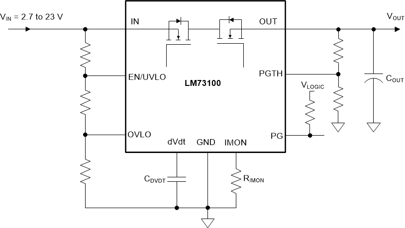
 简化版原理图
4 Revision History
Changes from Revision * (October 2020) to Revision A (December 2020)
- 将状态从“预告信息”更改为“量产数据”Go
5 Pin Configuration and Functions
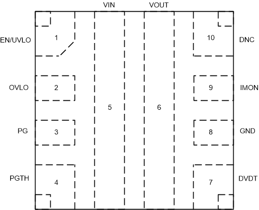
 Figure 5-1 LM73100 RPW Package 10-Pin QFN Top
View
Figure 5-1 LM73100 RPW Package 10-Pin QFN Top
View| PIN | TYPE | DESCRIPTION | |
|---|---|---|---|
| NAME | NO. | ||
| EN/UVLO |
1 | Analog Input | Active High Enable for the device. A Resistor Divider on this pin from input supply to GND can be used to adjust the Undervoltage Lockout threshold. Do not leave floating. Refer to Section 7.3.2 for more details. |
|
OVLO |
2 | Analog Input | A Resistor Divider on this pin from supply to GND can be used to adjust the Overvoltage Lockout threshold. This pin can also be used as an Active Low Enable for the device. Do not leave floating. Refer to Section 7.3.3 for more details. |
|
PG |
3 | Digital Output | Power Good indication. This is an Open Drain signal which is asserted High when the internal powerpath is fully turned ON and PGTH input exceeds a certain threshold. Refer to Section 7.3.9 for more details. |
|
PGTH |
4 | Analog Input | Power Good Threshold. Refer to Section 7.3.9 for more details. |
|
IN |
5 |
Power | Power Input. |
|
OUT |
6 |
Power | Power Output. |
|
DVDT |
7 | Analog Output | A capacitor from this pin to GND sets the output turn on slew rate. Leave this pin floating for the fastest turn on slew rate. Refer to Section 7.3.4.1 for more details. |
|
GND |
8 |
Ground | This is the ground reference for all internal circuits and must be connected to system GND. |
|
IMON |
9 | Analog Output |
Analog load current monitor. The pin voltage can be used to monitor the output load current. An external resistor from this pin to ground sets the current monitor gain. Recommended to connect external clamp to limit the voltage below abs max rating in case of large current spikes. Connect to ground if not used. Do not leave floating. Refer to Section 7.3.5 for more details. |
|
DNC |
10 |
X |
Internal test pin. Do not connect anything on this pin. |
6 Specifications
6.1 Absolute Maximum Ratings
| Parameter | Pin | MIN | MAX | UNIT | |
|---|---|---|---|---|---|
| VIN | Maximum Input Voltage Range, –40 ℃ ≤ TJ ≤ 125 ℃ | IN | max (–15, VOUT - 21) | 28 | V |
| Maximum Input Voltage Range, –10 ℃ ≤ TJ ≤ 125 ℃ | max (–15, VOUT - 22) | 28 | V | ||
| VOUT | Maximum Output Voltage Range, –40 ℃ ≤ TJ ≤ 125 ℃ | OUT | –0.3 | min (28, VIN + 21) | |
| Maximum Output Voltage Range, –10 ℃ ≤ TJ ≤ 125 ℃ | –0.3 | min (28, VIN + 22) | |||
| VOUT,PLS | Minimum Output Voltage Pulse (< 1 µs) | OUT | –0.8 | ||
| VEN/UVLO | Maximum Enable Pin Voltage Range (2) | EN/UVLO | –0.3 | 6.5 | V |
| VOVLO | Maximum OVLO Pin Voltage Range (2) | OVLO | –0.3 | 6.5 | V |
| VdVdT | Maximum dVdT Pin Voltage Range | dVdt | Internally Limited | V | |
| VPGTH | Maximum PGTH Pin Voltage Range (2) | PGTH | –0.3 | 6.5 | V |
| VPG | Maximum PG Pin Voltage Range | PG | –0.3 | 6.5 | V |
| VIMON | Maximum IMON Pin Voltage Range | IMON | 1.8 | V | |
| IMAX | Maximum Continuous Switch Current | IN to OUT | 5.5 | A | |
| TJ | Junction temperature | Internally Limited | °C | ||
| TLEAD | Maximum Lead Temperature | 300 | °C | ||
| TSTG | Storage temperature | –65 | 150 | °C | |