-
UCC27324-Q1 双通道 4A 峰值高速低侧电源 MOSFET 驱动器
- 1
- 1 特性
- 2 应用
- 3 说明
- 4 Pin Configuration and Functions
-
5 Specifications
- 5.1 Absolute Maximum Ratings
- 5.2 ESD Ratings
- 5.3 Recommended Operating Conditions
- 5.4 Thermal Information
- 5.5 Overall Electrical Characteristics
- 5.6 Power Dissipation Characteristics
- 5.7 Input (INA, INB) Electrical Characteristics
- 5.8 Output (OUTA, OUTB) Electrical Characteristics
- 5.9 Switching Characteristics
- 5.10 Typical Characteristics
- 6 Detailed Description
- 7 Application and Implementation
- 8 Power Supply Recommendations
- 9 Layout
- 10Device and Documentation Support
- 11Revision History
- 12Mechanical, Packaging, and Orderable Information
- 重要声明
Data Sheet
UCC27324-Q1 双通道 4A 峰值高速低侧电源 MOSFET 驱动器
本资源的原文使用英文撰写。 为方便起见,TI 提供了译文;由于翻译过程中可能使用了自动化工具,TI 不保证译文的准确性。 为确认准确性,请务必访问 ti.com 参考最新的英文版本(控制文档)。
1 特性
- 符合汽车应用要求
- 业界通用引脚排列
- 可在米勒平坦区提供 ±4A 的高电流驱动
- 即使在低电源电压下也能实现高效的恒流源
- 与电源电压无关的 TTL 和 CMOS 兼容输入
- 1.8nF 负载时的上升时间和下降时间典型值分别为 20ns 和 15ns
- 输入下降和上升时的典型传播延迟时间分别为 25ns 和 35ns
- 电源电压为 4V 至 15V
- 电源电流为 0.3mA
- 可以并联双输出以获得更高的驱动电流
- TJ 额定值范围为 –40°C 至 125°C
- 并联双极和 CMOS 晶体管的 TrueDrive™ 输出架构
2 应用
- 开关电源供电
- 直流/直流转换器
- 电机控制器
- 线路驱动器
- D 类开关放大器
3 说明
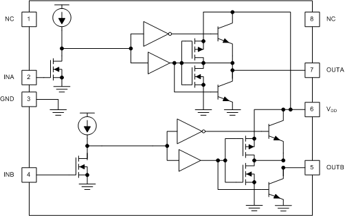
UCC27324-Q1 高速双路 MOSFET 驱动器可向容性负载提供大峰值电流。通过使用本身能够最大限度减少击穿电流的设计,这些驱动器可在 MOSFET 开关切换期间,在米勒平坦区域提供最需要的 4A 电流。独特的双极和 MOSFET 混合输出级并联,可在低电源电压下实现高效的拉电流和灌电流。
该器件采用标准的 SOIC-8 (D) 封装。
器件信息
| 器件型号 | 封装(1) | 封装尺寸(标称值) |
|---|---|---|
| UCC27324-Q1 | SOIC (8) | 4.90mm × 3.91mm |
(1) 如需了解所有可用封装,请参阅数据表末尾的可订购产品附录。
 方框图
方框图4 Pin Configuration and Functions

NC – No internal connection
Figure 4-1 D Package8-Pin SOICTop ViewTable 4-1 Pin Functions
| PIN | I/O | DESCRIPTION | |
|---|---|---|---|
| NO. | NAME | ||
| 1 | NC | — | No connection. Should be grounded. |
| 2 | INA | I | Input A. Input signal of the A driver. Has logic-compatible threshold and hysteresis. If not used, this input should be tied to either VDD or GND. It should not be left floating. |
| 3 | GND | — | Common ground. Should be connected very closely to the source of the power MOSFET that the driver is driving. |
| 4 | INB | I | Input B. Input signal of the B driver. Has logic-compatible threshold and hysteresis. If not used, this input should be tied to either VDD or GND. It should not be left floating. |
| 5 | OUTB | O | Driver output B. The output stage can provide 4-A drive current to the gate of a power MOSFET. |
| 6 | VDD | I | Supply. Supply voltage and the power input connection for this device. |
| 7 | OUTA | O | Driver output A. The output stage can provide 4-A drive current to the gate of a power MOSFET. |
| 8 | NC | — | No connection. Should be grounded. |