• Menu
  • Product
  • Email
  • PDF
  • Order now
  • IWR1443 单芯片 76 至 81GHz 毫米波传感器

    • ZHCSHP9C May   2017  – October 2018 IWR1443

      PRODUCTION DATA.  

  • CONTENTS
  • SEARCH
  • IWR1443 单芯片 76 至 81GHz 毫米波传感器
  1. 1器件概述
    1. 1.1 特性
    2. 1.2 应用
    3. 1.3 说明
    4. 1.4 功能框图
  2. 2修订历史记录
  3. 3Device Comparison
    1. 3.1 Related Products
  4. 4Terminal Configuration and Functions
    1. 4.1 Pin Diagram
    2. 4.2 Signal Descriptions
      1. Table 4-1 Signal Descriptions
    3. 4.3 Pin Multiplexing
  5. 5Specifications
    1. 5.1 Absolute Maximum Ratings
    2. 5.2 ESD Ratings
    3. 5.3 Power-On Hours (POH)
    4. 5.4 Recommended Operating Conditions
    5. 5.5 Power Supply Specifications
    6. 5.6 Power Consumption Summary
    7. 5.7 RF Specification
    8. 5.8 Thermal Resistance Characteristics for FCBGA Package [ABL0161]
    9. 5.9 Timing and Switching Characteristics
      1. 5.9.1  Power Supply Sequencing and Reset Timing
      2. 5.9.2  Synchronized Frame Triggering
      3. 5.9.3  Input Clocks and Oscillators
        1. 5.9.3.1 Clock Specifications
      4. 5.9.4  Multibuffered / Standard Serial Peripheral Interface (MibSPI)
        1. 5.9.4.1 Peripheral Description
        2. 5.9.4.2 MibSPI Transmit and Receive RAM Organization
          1. Table 5-8  SPI Timing Conditions
          2. Table 5-9  SPI Master Mode Switching Parameters (CLOCK PHASE = 0, SPICLK = output, SPISIMO = output, and SPISOMI = input)
          3. Table 5-10 SPI Master Mode Switching Parameters (CLOCK PHASE = 1, SPICLK = output, SPISIMO = output, and SPISOMI = input)
        3. 5.9.4.3 SPI Slave Mode I/O Timings
          1. Table 5-11 SPI Slave Mode Switching Parameters (SPICLK = input, SPISIMO = input, and SPISOMI = output)
        4. 5.9.4.4 Typical Interface Protocol Diagram (Slave Mode)
      5. 5.9.5  LVDS Interface Configuration
        1. 5.9.5.1 LVDS Interface Timings
      6. 5.9.6  General-Purpose Input/Output
        1. Table 5-13 Switching Characteristics for Output Timing versus Load Capacitance (CL)
      7. 5.9.7  Controller Area Network Interface (DCAN)
        1. Table 5-14 Dynamic Characteristics for the DCANx TX and RX Pins
      8. 5.9.8  Serial Communication Interface (SCI)
        1. Table 5-15 SCI Timing Requirements
      9. 5.9.9  Inter-Integrated Circuit Interface (I2C)
        1. Table 5-16 I2C Timing Requirements
      10. 5.9.10 Quad Serial Peripheral Interface (QSPI)
        1. Table 5-17 QSPI Timing Conditions
        2. Table 5-18 Timing Requirements for QSPI Input (Read) Timings
        3. Table 5-19 QSPI Switching Characteristics
      11. 5.9.11 JTAG Interface
        1. Table 5-20 JTAG Timing Conditions
        2. Table 5-21 Timing Requirements for IEEE 1149.1 JTAG
        3. Table 5-22 Switching Characteristics Over Recommended Operating Conditions for IEEE 1149.1 JTAG
      12. 5.9.12 Camera Serial Interface (CSI)
        1. Table 5-23 CSI Switching Characteristics
  6. 6Detailed Description
    1. 6.1 Overview
    2. 6.2 Functional Block Diagram
    3. 6.3 External Interfaces
    4. 6.4 Subsystems
      1. 6.4.1 RF and Analog Subsystem
        1. 6.4.1.1 Clock Subsystem
        2. 6.4.1.2 Transmit Subsystem
        3. 6.4.1.3 Receive Subsystem
        4. 6.4.1.4 Radio Processor Subsystem
      2. 6.4.2 Master (Control) System
      3. 6.4.3 Host Interface
    5. 6.5 Accelerators and Coprocessors
    6. 6.6 Other Subsystems
      1. 6.6.1 A2D Data Format Over CSI2 Interface
      2. 6.6.2 ADC Channels (Service) for User Application
        1. Table 6-2 GP-ADC Parameter
    7. 6.7 Identification
    8. 6.8 Boot Modes
      1. 6.8.1 Flashing Mode
      2. 6.8.2 Functional Mode
  7. 7Applications, Implementation, and Layout
    1. 7.1 Application Information
    2. 7.2 Reference Schematic
    3. 7.3 Layout
      1. 7.3.1 Layout Guidelines
      2. 7.3.2 Layout Example
      3. 7.3.3 Stackup Details
  8. 8Device and Documentation Support
    1. 8.1 Device Nomenclature
    2. 8.2 Tools and Software
    3. 8.3 Documentation Support
    4. 8.4 Community Resources
    5. 8.5 商标
    6. 8.6 静电放电警告
    7. 8.7 Export Control Notice
    8. 8.8 Glossary
  9. 9Mechanical, Packaging, and Orderable Information
    1. 9.1 Packaging Information
  10. 重要声明
search No matches found.
  • Full reading width
    • Full reading width
    • Comfortable reading width
    • Expanded reading width
  • Card for each section
  • Card with all content


DATA SHEET

IWR1443 单芯片 76 至 81GHz 毫米波传感器

本资源的原文使用英文撰写。 为方便起见,TI 提供了译文;由于翻译过程中可能使用了自动化工具,TI 不保证译文的准确性。 为确认准确性,请务必访问 ti.com 参考最新的英文版本(控制文档)。

1 器件概述

1.1 特性

  • FMCW 收发器
    • 集成式 PLL、发送器、接收器、基带和 A2D
    • 76 至 81GHz 覆盖范围,具有 4GHz 的连续带宽
    • 四个接收通道
    • 三个发送通道(可以同时使用两个通道)
    • 基于分数 N PLL 的超精确线性调频脉冲引擎
    • TX 功率:12dBm
    • RX 噪声系数:
      • 14dB(76 至 77GHz)
      • 15dB(77 至 81GHz)
    • 1MHz 时的相位噪声:
      • –95dBc/Hz(76 至 77GHz)
      • –93dBc/Hz(77 至 81GHz)
  • 内置的校准和自检
    • ARM®Cortex®基于 ARM® Cortex®-R4F 的无线电控制系统
    • 内置的固件 (ROM)
    • 针对频率和温度进行自校准的系统
  • 适用于嵌入式用户应用的片上可编程内核
    • 计时频率为 200MHz 的集成 Cortex®-R4F 微控制器
    • 片上引导加载程序支持自主模式(从 QSPI 闪存加载用户应用)
    • 集成外设
      • 具有 ECC 的内部存储器
      • 雷达硬件加速器(FFT、对数幅度计算等)
      • 集成计时器(看门狗以及多达四个 32 位计时器或两个 64 位计时器)
      • I2C(支持主模式和从模式)
      • 两个 SPI 端口
      • CAN 端口
      • 多达六个通用 ADC 端口
  • 支持分布式 应用
  • 主机接口
    • 通过 SPI 与外部处理器进行控制连接
    • 通过 MIPI D-PHY 和 CSI2 V1.1 与外部处理器进行数据连接
    • 用于故障报告的中断
  • IWR1443 高级 特性
    • 嵌入式自监控,无需使用主机处理器
    • 复基带架构
    • 嵌入式干扰检测功能
  • 电源管理
    • 内置的 LDO 网络,可增强 PSRR
    • I/O 支持双电压 3.3V/1.8V
  • 时钟源
    • 支持频率为 40MHz 的外部振荡器
    • 支持外部驱动、频率为 40MHz 的时钟(方波/正弦波)
  • 轻松的硬件设计
    • 0.65mm 间距、161 引脚 10.4mm × 10.4mm 覆晶 BGA 封装,可实现轻松组装和低成本 PCB 设计
    • 小尺寸解决方案
  • 运行条件
    • 结温范围:–40°C 至 105°C

1.2 应用

  • 用于测量距离、速度和角度的工业传感器
  • 液箱液位探测雷达
  • 位移感应
  • 现场发送器
  • 交通监控
  • 接近和位置感应
  • 安全和监控
  • 工厂自动化
  • 安全防护装置
IWR1443 front_pg_image.gifFigure 1-1 适用于工业应用的自主 传感器

1.3 说明

IWR1443 器件是一款能够在 76 至 81GHz 频带中运行且基于 FMCW 雷达技术的集成式单芯片毫米波传感器,具有高达 4GHz 的连续线性调频脉冲。该器件采用 TI 的低功耗 45nm RFCMOS 工艺进行构建,并且此解决方案在极小的封装中实现了前所未有的集成度。IWR1443 是适用于工业 应用 (如楼宇自动化、工厂自动化、无人机、物料处理、交通监控和监视)中的低功耗、自监控、超精确雷达系统的理想解决方案。

IWR1443 器件是一种自包含单芯片解决方案,能够简化 76 至 81GHz 频带中的毫米波传感器实施。IWR1443 包含一个具有内置 PLL 和模数转换器的单片实施 3TX、4RX 系统。该器件包含一个支持复数 FFT 和 CFAR 检测且完全可配置的硬件加速器。此外,该器件还包含两个基于 ARM R4F 的处理器子系统:一个处理器子系统用于主控制和其他算法;另一个处理器子系统负责前端配置、控制和校准。简单编程模型更改可支持各种传感器实施,并且能够进行动态重新配置,从而实现多模式传感器。此外,该器件作为完整的平台解决方案进行提供,该解决方案包括硬件参考设计、软件驱动程序、样例配置、API 指南、培训以及用户文档。

器件信息(1)

器件编号 封装 封装尺寸
IWR1443FQAGABLR(卷带) FCBGA (161) 10.4mm × 10.4mm
IWR1443FQAGABL(托盘)
(1) 更多信息请参见 Section 9,机械封装和可订购产品信息。

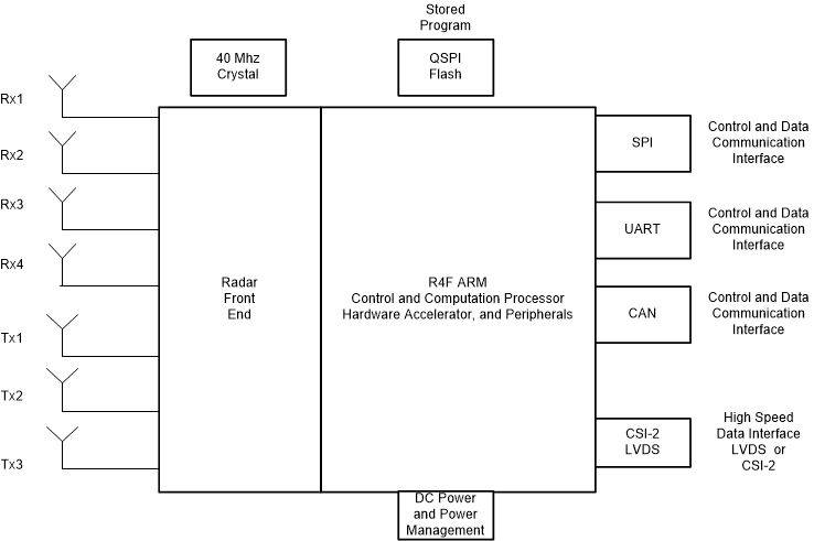
1.4 功能框图

IWR1443 fbd_swrs211.gif

2 修订历史记录

Changes from February 20, 2018 to October 31, 2018 (from B Revision (February 2018) to C Revision)

  • 将 RX 噪声系数从“15dB(76 至 77GHz)”更新成了“14dB(76 至 77GHz)”Go
  • 将 RX 噪声系数从“16dB(77 至 81GHz)”更新成了“15dB(77 至 81GHz)”Go
  • 将 1MHz 时的相位噪声从“–94dBc/Hz(76 至 77GHz)”更新成了“–95dBc/Hz(76 至 77GHz)”Go
  • 将 1MHz 时的相位噪声从“–91dBc/Hz(77 至 81GHz)”更新成了“–93dBc/Hz(77 至 81GHz)”Go
  • 从“...的高速数据接口”项目中删除了“(即中间数据)”Go
  • 从外部驱动振荡器和外部驱动时钟中删除了 50MHzGo
  • 更新了“器件信息”Go
  • 从功能方框图 中删除了“VMON”框Go
  • Added table note to "Number of transmitters" in Device Features ComparisonGo
  • Updated IWR1443 and IWR1642 Product status from AI to PDGo
  • Updated OSC_CLKOUTGo
  • Updated P7 from "Open Drain" to "Pull Up'Go
  • Updated B10 DESCRIPTIONGo
  • Updated A10, A13, A2, and B2 DESCRIPTIONGo
  • Removed footnote from Flash programming and RS232 UARTGo
  • Updated ESD RatingsGo
  • Updated/Changed Power-On Hours (POH)Go
  • Updated VIOIN in Recommended Operating ConditionsGo
  • Updated VIL 1.8V MAX from "3*VIOIN" to "0.3*VIOIN"Go
  • Updated VOH in Recommended Operating ConditionsGo
  • Updated VOH in Recommended Operating ConditionsGo
  • Updated Recommended Operating ConditionsGo
  • Added "VNWA" to 1.2 V Supply in Power Supply Rails CharacteristicsGo
  • Completely updated Ripple Specifications tableGo
  • Updated Receiver Noise figure values in RF SpecificationGo
  • Updated Receiver 1-dB compression point value from "–5" to "–8"Go
  • Updated "IQ gain mismatch" to "Image Rejection Ratio (IMRR)"Go
  • Removed IQ phase mismatch from RF SpecificationGo
  • Updated RF Specification tableGo
  • Updated footnote in RF SpecificationGo
  • Removed 1v4 signal from Device Wakeup Go
  • Updated Device Wake-up SequenceGo
  • Updated Synchronized Frame Triggering text Go
  • Added Synchronized Frame Triggering subsectionGo
  • Removed TLag from Frame Trigger Timing table Go
  • Updated Crystal Implementation noteGo
  • Updated/Changed fP Parallel resonance crystal frequency from " 40, 50" to "40"Go
  • Completely updated External Clock Mode SpecificationsGo
  • Updated SPI Slave Mode Timing RequirementsGo
  • Added LVDS Interface ConfigurationGo
  • Updated LVDS Interface Lane Config imageGo
  • Updated Timing ParametersGo
  • Updated LVDS Electrical Characteristics Go
  • Updated Timing Requirements for QSPI Input (Read) TimingsGo
  • Added Q12, Q13, Q14, and Q15 to QSPI Switching CharacteristicsGo
  • Updated Data bit rate from 900 Mbps to 600 MbpsGo
  • Removed TCLK-SETTLE and THS-SETTLEGo
  • Updated Clock Subsystem diagramGo
  • Updated/Changed Transmit Subsystem (Per Channel)Go
  • Removed Master System Memory MapGo
  • Updated Host InterfaceGo
  • Updated text in "A2D Data Format Over CSI2 Interface"Go
  • Updated text in ADC Channels (Service) for User ApplicationGo
  • Completely updated GP-ADC Parameter tableGo
  • Updated text in Functional ModeGo
  • Updated Application InformationGo
  • Updated Device NomenclatureGo

3 Device Comparison

Table 3-1 Device Features Comparison

FUNCTION IWR1443 IWR1642
Number of receivers 4 4
Number of transmitters 3 2
On-chip memory 576KB 1.5MB
Max I/F (Intermediate Frequency) (MHz) 15 5
Max real sampling rate (Msps) 37.5 12.5
Max complex sampling rate (Msps) 18.75 6.25
Processor
MCU (R4F) Yes Yes
DSP (C674x) — Yes
Peripherals
Serial Peripheral Interface (SPI) ports 1 2
Quad Serial Peripheral Interface (QSPI) Yes Yes
Inter-Integrated Circuit (I2C) interface 1 1
Controller Area Network (DCAN) interface Yes Yes
Trace — Yes
PWM — Yes
Hardware In Loop (HIL/DMM) — Yes
GPADC Yes Yes
LVDS/Debug Yes Yes
CSI2 Yes —
Hardware accelerator Yes —
1-V bypass mode Yes Yes
JTAG Yes Yes
Product status Product Preview (PP),
Advance Information (AI),
or Production Data (PD)
PD(1) PD(1)
(1) PRODUCTION DATA information is current as of publication date. Products conform to specifications per the terms of the Texas Instruments standard warranty. Production processing does not necessarily include testing of all parameters.

3.1 Related Products

For information about other devices in this family of products or related products see the links that follow.

    mmWave SensorsTI’s mmWave sensors rapidly and accurately sense range, angle and velocity with less power using the smallest footprint mmWave sensor portfolio for industrial applications.
    mmWave IWRThe Texas Instruments IWR1xxx family of mmWave Sensors are highly integrated and built on RFCMOS technology operating in 76- to 81-GHz frequency band. The devices have a closed-loop PLL for precise and linear chirp synthesis, includes a built-in radio processor (BIST) for RF calibration and safety monitoring. The devices have a very small-form factor, low power consumption, and are highly accurate. Industrial applications from long range to ultra short range can be realized using these devices.
    Companion Products for IWR1443Review products that are frequently purchased or used in conjunction with this product.
    IWR1443 Reference DesignsThe IWR1443 TI Designs Reference Design Library is a robust reference design library spanning analog, embedded processor and connectivity. Created by TI experts to help you jump-start your system design, all TI Designs include schematic or block diagrams, BOMs, and design files to speed your time to market. Search and download designs at ti.com/tidesigns.
    Power Optimization for IWR1443 77GHz-Level Transmitter Reference DesignThe TIDEP-0091 highlights strategies for power optimization of a IWR1443 76- to 81-GHz mmWave sensor in tank level-probing applications, displacement sensors, 4- to 20-mA sensors, and other low-power applications for detecting range with high accuracy in minimal power envelope.


Texas Instruments

© Copyright 1995-2025 Texas Instruments Incorporated. All rights reserved.
Submit documentation feedback | IMPORTANT NOTICE | Trademarks | Privacy policy | Cookie policy | Terms of use | Terms of sale