• Menu
  • Product
  • Email
  • PDF
  • Order now
  • TAS5634 300W 立体声/600W 单声道高清数字输入、58V D 类放大器功率级

    • ZHCSH20 October   2017 TAS5634

      PRODUCTION DATA.  

  • CONTENTS
  • SEARCH
  • TAS5634 300W 立体声/600W 单声道高清数字输入、58V D 类放大器功率级
  1. 1 特性
  2. 2 应用
  3. 3 说明
  4. 4 修订历史记录
  5. 5 Device Comparison
  6. 6 Pin Configuration and Functions
  7. 7 Specifications
    1. 7.1 Absolute Maximum Ratings
    2. 7.2 ESD Ratings
    3. 7.3 Recommended Operating Conditions
    4. 7.4 Thermal Information
    5. 7.5 Audio Specification Stereo (BTL)
    6. 7.6 Audio Specifications Mono (PBTL)
    7. 7.7 Audio Specification 4 Channels (SE)
    8. 7.8 Electrical Characteristics
    9. 7.9 Typical Characteristics
      1. 7.9.1 BTL Configuration
      2. 7.9.2 PBTL Configuration
      3. 7.9.3 SE Configuration
  8. 8 Detailed Description
    1. 8.1 Overview
    2. 8.2 Functional Block Diagrams
    3. 8.3 Feature Description
      1. 8.3.1  Closed-Loop Architecture
      2. 8.3.2  Power Supplies
        1. 8.3.2.1 BST, Bootstrap Supply
        2. 8.3.2.2 PVDD, Output Stage Power Supply
        3. 8.3.2.3 GVDD, Gate-Drive Power Supply
        4. 8.3.2.4 VDD Supply, Internal Regulators (DVDD and AVDD)
      3. 8.3.3  System Power-Up / Power-Down Sequence
        1. 8.3.3.1 Powering Up
        2. 8.3.3.2 Powering Down
      4. 8.3.4  Startup and Shutdown Ramp Sequence (C_START)
      5. 8.3.5  Device Protection System
      6. 8.3.6  Overload and Short Circuit Current Protection
      7. 8.3.7  DC Speaker Protection
      8. 8.3.8  Pin-To-Pin Short Circuit Protection (PPSC)
      9. 8.3.9  Overtemperature Protection
      10. 8.3.10 Overtemperature Warning, OTW
      11. 8.3.11 Undervoltage Protection (UVP) and Power-On Reset (POR)
      12. 8.3.12 Error Reporting
      13. 8.3.13 Fault Handling
      14. 8.3.14 System Design Consideration
    4. 8.4 Device Functional Modes
      1. 8.4.1 Stereo, Bridge-tied Load (BTL)
      2. 8.4.2 Mono, Paralleled Bridge-tied Load (PBTL)
      3. 8.4.3 4-Channel, Single-ended (SE)
      4. 8.4.4 BD Modulation
      5. 8.4.5 Device Reset
      6. 8.4.6 Unused Output Channels
  9. 9 Application and Implementation
    1. 9.1 Application Information
    2. 9.2 Typical Applications
      1. 9.2.1 Typical BTL Application
        1. 9.2.1.1 Design Requirements
        2. 9.2.1.2 Detailed Design Procedure
        3. 9.2.1.3 Pin Connections
        4. 9.2.1.4 Application Curves
      2. 9.2.2 Typical PBTL Configuration
        1. 9.2.2.1 Application Curves
      3. 9.2.3 Typical SE Configuration
        1. 9.2.3.1 Application Curves
  10. 10Power Supply Recommendations
    1. 10.1 Power Supplies
    2. 10.2 Bootstrap Supply
  11. 11Layout
    1. 11.1 Layout Guidelines
      1. 11.1.1 PCB Material Recommendation
      2. 11.1.2 PVDD Capacitor Recommendation
      3. 11.1.3 Decoupling Capacitor Recommendation
      4. 11.1.4 Circuit Component Requirements
      5. 11.1.5 Printed Circuit Board Requirements
    2. 11.2 Layout Example
  12. 12器件和文档支持
    1. 12.1 接收文档更新通知
    2. 12.2 社区资源
    3. 12.3 商标
    4. 12.4 静电放电警告
    5. 12.5 Glossary
  13. 13机械、封装和可订购信息
  14. 重要声明
search No matches found.
  • Full reading width
    • Full reading width
    • Comfortable reading width
    • Expanded reading width
  • Card for each section
  • Card with all content


DATA SHEET

TAS5634 300W 立体声/600W 单声道高清数字输入、58V D 类放大器功率级

本资源的原文使用英文撰写。 为方便起见,TI 提供了译文;由于翻译过程中可能使用了自动化工具,TI 不保证译文的准确性。 为确认准确性,请务必访问 ti.com 参考最新的英文版本(控制文档)。

1 特性

  • PWM 输入、D 类放大器功率级,与 TI 数字输入 (I2S) 音频处理器和调制器兼容
  • 高清集成闭环反馈,具备以下特性:
    • 在为 6Ω 负载提供 1W 功率时,THD 为 0.025%
    • PSRR 大于 70dB(无输入信号)
    • SNR 大于 105dB(A 加权)
  • 10% THD+N 时的输出功率
    • 600W/3Ω(PBTL 单声道配置)
    • 300W/6Ω(BTL 立体声配置)
    • 230W/8Ω(BTL 立体声配置)
  • 1% THD+N 时的输出功率
    • 465W/3Ω(PBTL 单声道配置)
    • 240W/6Ω(BTL 立体声配置)
    • 180W/8Ω(BTL 立体声配置)
  • 集成式 80 mΩ MOSFET,可降低散热器尺寸
    • 满量程输出功率下的效率大于 91%
    • 1/8 量程输出功率下的效率大于 75%
  • 启动时无喀哒声
  • 器件保护:欠压保护、过热保护、过流保护、短路保护和直流扬声器保护
  • 适用于 G 类电源控制的预削波输出信号
  • 44 引脚 HTSSOP (DDV) 封装,顶部带有散热焊盘

2 应用

  • 电动扬声器
  • 低音炮
  • 微型组件系统
  • 条形音箱
  • 专业和公共广播 (PA) 扬声器

3 说明

TAS5634 是一款 PWM 输入 D 类放大器功率级,可在 58V 标称电源电压下提供 2 x 300W (6Ω) 或 1 x 600W (3Ω) 的输出功率。58V 电源电压支持较高阻抗的扬声器负载,其中 BTL 为 6Ω,PBTL 为 3Ω。集成式 MOSFET 和全新栅极驱动方案具有较高的峰值效率和较低的空闲损耗,能够减小散热器解决方案尺寸。

TAS5634 使用闭环反馈设计,具有恒定的电压增益。开关模式电源 (SMPS) 的使用,使得内部匹配的增益电阻器可确保实现较高的电源抑制比 (PSRR) 和较低的输出噪声。

TAS5634 是一款兼容 TI 的数字输入 (I2S) 音频处理器和调制器产品组合的全集成式功率级,与 TAS5548 和 TAS5558 类似,也是一个完整的数字输入 D 类放大器。TAS5634 采用表面安装 44 引脚 HTSSOP 封装,是 PWM 输入 D 类功率级兼容引脚产品系列(包括 TAS5612LA、TAS5614LA 和 TAS5624A)中的一员。 PowerPAD™ PurePath™ 高清

器件信息(1)

器件型号 封装 封装尺寸(标称值)
TAS5634 HTSSOP 14.00mm x 6.10mm
  1. 如需了解所有可用封装,请参阅数据表末尾的可订购产品附录。

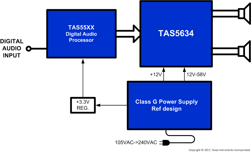
简化电路原理图

TAS5634 FrontPageApplication.gif

4 修订历史记录

日期 修订版本 说明
2017 年 10 月 * 首次公开发布。

5 Device Comparison

DEVICE NAME DESCRIPTION PVDD VOLTAGE (Nom.) RDrain-to-Source
TAS5612LA 125 W Stereo / 250 W Mono HD Digital-Input Power Stage 32.5 V 60 mΩ
TAS5614LA 150 W Stereo / 300 W Mono HD Digital-Input Power Stage 36 V 60 mΩ
TAS5624A 200 W Stereo / 400 W Mono HD Digital-Input Power Stage 36 V 40 mΩ
TAS5634 300 W Stereo / 600 W Mono HD Digital-Input Power Stage 58 V 80 mΩ

6 Pin Configuration and Functions

The TAS5634 is available in a thermally-enhanced, 44-Pin HTSSOP package (DDV).

The package contains a PowerPAD™ that is located on the top side of the device for convenient thermal coupling to a heatsink.

DDV Package
44 Pin (HTSSOP)
Top View

Pin Functions

PIN I/O/P(1) DESCRIPTION Sections
NAME NO.
AVDD 13 P Analog internal voltage regulator output. Place 1 μF capacitor to GND.
BST_A 44 P Bootstrap pin, A-side. Connect 0.33 nF ceramic capacitor to OUT_A.
BST_B 43 P Bootstrap pin, B-side. Connect 0.33 nF ceramic capacitor to OUT_B.
BST_C 24 P Bootstrap pin, C-side. Connect 0.33 nF ceramic capacitor to OUT_C.
BST_D 23 P Bootstrap pin, D-side. Connect 0.33 nF ceramic capacitor to OUT_D.
CLIP 18 O Clipping warning; open drain; active low. Connect 10 kΩ pull-up resistor to DVDD to monitor. If unused, do not connect.
C_START 7 O Startup ramp timing control pin. Connect capacitor to ground. 330nF for BTL / PBTL mode. 1 μF for SE mode.
DVDD 8 P Digital internal voltage regulator output. Place 1 μF capacitor to GND.
FAULT 16 O Fault signal output, open drain; active low. Connect 10 kΩ pull-up resistor to DVDD to monitor. If unused, do not connect.
GND 9, 10, 11, 12, 25, 26, 33, 34, 41, 42 P Ground.
GVDD_AB 1 P Gate-drive voltage supply; AB-side. Place 100 nF decoupling capacitor to GND.
GVDD_CD 22 P Gate-drive voltage supply; CD-side. Place 100 nF decoupling capacitor to GND.
INPUT_A 5 I PWM Input signal for half-bridge A. If unused, connect INPUT_A to GND.
INPUT_B 6 I PWM Input signal for half-bridge B. If unused, connect INPUT_B to GND.
INPUT_C 14 I PWM Input signal for half-bridge C. If unused, connect INPUT_C to GND.
INPUT_D 15 I PWM Input signal for half-bridge D. If unused, connect INPUT_D to GND.
M1 19 I Mode selection 1.
M2 20 I Mode selection 2.
M3 21 I Mode selection 3.
OC_ADJ 3 O Over-Current threshold programming pin. Connect programming resistor to GND. Use 27 kΩ for typical applications.
OTW 17 O Over-temperature warning; open drain; active low. Connect 10 kΩ pull-up resistor to DVDD to monitor. If unused, do not connect.
OUT_A 39, 40 O Output, half-bridge A. If unused, remove BST_A capacitor and GND INPUT_A pin. Output pins can be left floating.
OUT_B 35 O Output, half-bridge B. If unused, remove BST_B capacitor and GND INPUT_B pin. Output pins can be left floating.
OUT_C 32 O Output, half-bridge C. If unused, remove BST_C capacitor and GND INPUT_C pin. Output pins can be left floating.
OUT_D 27, 28 O Output, half-bridge D. If unused, remove BST_D capacitor and GND INPUT_D pin. Output pins can be left floating.
PVDD_AB 36, 37, 38 P PVDD supply for half-bridge A and B. Place a minimum of 1 μF decoupling capacitor near PVDD_AB pin.
PVDD_CD 29, 30, 31 P PVDD supply for half-bridge C and D. Place a minimum of 1 μF decoupling capacitor near PVDD_CD pin.
RESET 4 I Device reset pin; active low.
VDD 2 P 12V power supply input for internal analog and digital voltage regulators.
PowerPAD™ P Ground, connect to grounded heat sink.
(1) I = Input, O = Output, P = Power

Table 1. Mode Selection Pins

MODE PINS PWM Input(1) Output Configuration Input A Input B Input C Input D DC Speaker Protection(2) Mode C_START Capacitor
M3 M2 M1
0 0 0 2N 2 x BTL PWMa PWMb PWMc PWMd Enabled AD 330 nF
0 0 1 1N(3) 2 x BTL PWMa Unused PWMc Unused Enabled AD 330 nF
0 1 0 2N 2 x BTL PWMa PWMb PWMc PWMd Disabled AD or BD 330 nF
0 1 1 2N/1N(3) 1 x BTL + 2 x SE(4) PWMa PWMb PWMc PWMd Enabled (BTL only) AD 1 μF
1 0 0 2N 1 x PBTL PWMa PWMb 0 0 Enabled AD 330 nF
1 0 0 1N(3) 1 x PBTL PWMa Unused 0 1 Enabled AD 330 nF
1 0 0 2N 1 x PBTL PWMa PWMb 1 0 Disabled AD or BD 330 nF
1 0 1 1N1 4 x SE(5) PWMa PWMb PWMc PWMd Disabled AD 1 μF
(1) The 1N and 2N naming convention is used to indicate the number of PWM lines to the power stage per channel in a specific mode.
(2) DC Speaker Protection is disabled in BD mode due to in phase inductor ripple current.
(3) Using 1N interface in BTL and PBTL mode results in increased DC offset on the output terminals.
(4) In [011] 1 x BTL + 2 x SE mode, Output A and B refers to the BTL channel, and Output C and D the SE channels
(5) The 4xSE mode can be used as 1 x BTL + 2 x SE configuration by feeding a 2N PWM signal to either INPUT_AB or INPUT_CD

7 Specifications

7.1 Absolute Maximum Ratings

over operating free-air temperature range unless otherwise noted (1)
MIN MAX UNIT
VDD to GND, GVDD_X(3) to GND –0.3 13.2 V
PVDD_X(3) to GND –0.3 65 V
PVDD_X(3) to GND(2) (Less than 8ns transient) -0.3 71 V
OUT_X to GND -0.3 65 V
OUT_X to GND(2) (Less than 8ns transient) -7 71 V
BST_X to OUT_X(3) –0.3 13.2 V
DVDD to GND –0.3 4.2 V
AVDD to GND –0.3 8.5 V
OC_ADJ, M1, M2, M3, C_START, INPUT_X to GND –0.3 4.2 V
RESET, FAULT, OTW, CLIP, to GND –0.3 4.2 V
Maximum continuous sink current (FAULT, OTW, CLIP) 9 mA
Maximum operating junction temperature range, TJ 0 150 °C
Storage temperature, Tstg –40 150 °C
(1) Stresses beyond those listed under Absolute Maximum Ratings may cause permanent damage to the device. These are stress ratings only, and functional operation of the device at these or any other conditions beyond those indicated under Recommended Operating Conditions is not implied. Exposure to absolute-maximum-rated conditions for extended periods may affect device reliability.
(2) These voltages represents the DC voltage + peak AC waveform measured at the terminal of the device in all conditions.
(3) GVDD_X and PVDD_X represents a full bridge gate drive or power supply. GVDD_X is GVDD_AB or GVDD_CD, PVDD_X is PVDD_AB or PVDD_CD

7.2 ESD Ratings

VALUE UNIT
V(ESD) Electrostatic discharge Human-body model (HBM), per ANSI/ESDA/JEDEC JS-001(1) (3) ±2000 V
Electrostatic discharge Charged-device model (CDM), per JEDEC specification JESD22-C101(2) (3) ±500 V
(1) JEDEC document JEP155 states that 500-V HBM allows safe manufacturing with a standard ESD control process.
(2) JEDEC document JEP157 states that 250-V CDM allows safe manufacturing with a standard ESD control process.
(3) Maximum BST_X to GND voltage is the sum of maximum PVDD to GND and GVDD to GND voltages minus a diode drop.

7.3 Recommended Operating Conditions

MIN TYP MAX UNIT
PVDD_X Full-bridge supply DC supply voltage 12 58 62 V
GVDD_X Supply for logic regulators and gate-drive circuitry DC supply voltage 10.8 12 13.2 V
VDD Digital regulator supply voltage DC supply voltage 10.8 12 13.2 V
RL Load impedance BTL Output filter: L = 15 uH, 0.68 µF 5 8 Ω
PBTL 3 4
SE 3 4
LOUTPUT Output filter inductance Minimum inductance at overcurrent limit, including inductor tolerance, temperature and possible inductor saturation 7 15 μH
fPWM PWM frame rate 352 384 500 kHz
CPVDD PVDD close decoupling capacitors 0.44 1 μF
C_START Startup ramp capacitor BTL and PBTL configuration 330 nF
SE and 1xBTL + 2xSE configuration 1 μF
ROC Over-current programming resistor, Resistor tolerance = 5% 24 27 33 kΩ
ROC_LATCHED Over-current programming resistor, Resistor tolerance = 5% 47 56 62 kΩ
TJ Junction temperature 0 125 °C

7.4 Thermal Information

THERMAL METRIC(1) TAS5634 UNIT
DDV (HTSSOP)
44 PINS
RθJA Junction-to-ambient thermal resistance 2.6 °C/W
RθJC(top) Junction-to-case (top) thermal resistance 0.4 °C/W
RθJB Junction-to-board thermal resistance 2.0 °C/W
ψJT Junction-to-top characterization parameter 0.4 °C/W
ψJB Junction-to-board characterization parameter 1.9 °C/W
RθJC(bot) Junction-to-case (bottom) thermal resistance n/a °C/W
(1) For more information about traditional and new thermal metrics, see the Semiconductor and IC Package Thermal Metrics application report.

7.5 Audio Specification Stereo (BTL)

Audio performance is recorded as a chipset consisting of a TAS5548 PWM Processor (AD-mode, modulation index limited to 97.7%) and a TAS5634 power stage with PCB and system configurations in accordance with recommended guidelines. Audio frequency = 1 kHz, PVDD_X = 58 V, GVDD_X = 12 V, RL = 6 Ω, fS = 384 kHz, ROC = 30 kΩ, TC = 75°C, Output Filter: LDEM = 15 μH, CDEM = 680 nF, unless otherwise noted.
PARAMETER TEST CONDITIONS MIN TYP MAX UNIT
PO Power output per channel RL = 8 Ω, 10% THD+N 230 W
RL = 6 Ω, 10% THD+N Tc = 25°C 300
RL = 6 Ω, 10% THD+N 295
RL = 8 Ω, 1% THD+N 180
RL = 6 Ω, 1% THD+N 240
THD+N Total harmonic distortion + noise 1 W, 1 kHz signal 0.025 %
Vn Output integrated noise A-weighted, AES17 measuring filter, dither off, noise shaper off(1) 215 μV
VOS Output offset voltage No signal 50 mV
SNR Signal-to-noise ratio(2) A-weighted, AES17 measuring filter, noise shaper off 105 dB
DNR Dynamic range A-weighted, –60 dBFS (rel 1% THD+N), noise shaper on 102 dB
Pidle Power dissipation due to Idle losses (IPVDD_X) PO = 0, channels switching(3) 8.6 W
(1) It is recommended to turn off PWM processor noise shaper while no audio present for lowest output noise
(2) SNR is calculated relative to 1% THD-N output level.
(3) Actual system idle losses also are affected by core losses of output inductors.

7.6 Audio Specifications Mono (PBTL)

Audio performance is recorded as a chipset consisting of a TAS5548 PWM Processor (AD-mode, modulation index limited to 97.7%) and a TAS5634 power stage with PCB and system configurations in accordance with recommended guidelines. Audio frequency = 1 kHz, PVDD_X = 58 V, GVDD_X = 12 V, RL = 3 Ω, fS = 384 kHz, ROC = 30 kΩ, TC = 75°C, Output Filter: LDEM = 15 μH, CDEM = 680 nF, CDCB = 470 µF, unless otherwise noted.
PARAMETER TEST CONDITIONS MIN TYP MAX UNIT
PO Power output per channel RL = 4 Ω, 10% THD+N 460 W
RL = 3 Ω, 10% THD+N 590
RL = 3 Ω, 10% THD+N, PVDD = 58.5V 600
RL = 4 Ω, 1% THD+N 365
RL = 3 Ω, 1% THD+N 465
THD+N Total harmonic distortion + noise 1 W, 1 kHz signal 0.04 %
Vn Output integrated noise A-weighted, AES17 measuring filter, dither off, noise shaper off (1) 214 μV
VOS Output offset voltage No signal 50 mV
SNR Signal-to-noise ratio(2) A-weighted, AES17 measuring filter, noise shaper off 105 dB
DNR Dynamic range A-weighted, -60dBFS (rel 1% THD+N), noise shaper on 102 dB
Pidle Power dissipation due to Idle losses (IPVDD_X) PO = 0, channels switching(3) 8.6 W
(1) It is recommended to turn off PWM processor noise shaper while no audio present for lowest output noise
(2) SNR is calculated relative to 1% THD-N output level.
(3) Actual system idle losses also are affected by core losses of output inductors.

7.7 Audio Specification 4 Channels (SE)

Audio performance is recorded as a chipset consisting of a TAS5548 PWM Processor (AD-mode, modulation index limited to 97.7%) and a TAS5634 power stage with PCB and system configurations in accordance with recommended guidelines. Audio frequency = 1 kHz, PVDD_X = 58 V, GVDD_X = 12 V, RL = 3 Ω, fS = 384 kHz, ROC = 30 kΩ, TC = 75°C, Output Filter: LDEM = 15 μH, CDEM = 680 nF, CDCB = 470 µF, unless otherwise noted.
PARAMETER TEST CONDITIONS MIN TYP MAX UNIT
PO Power output per channel RL = 4 Ω, 10% THD+N 110 W
RL = 3 Ω, 10% THD+N Tc = 25°C 150
RL = 3 Ω, 10% THD+N 145
RL = 4 Ω, 1% THD+N 90
RL = 3 Ω, 1% THD+N 115
THD+N Total harmonic distortion + noise 1 W, 1 kHz signal 0.05 %
Vn Output integrated noise A-weighted, AES17 measuring filter, dither off, noise shaper off(1) 145 μV
SNR Signal-to-noise ratio(2) A-weighted, AES17 measuring filter, noise shaper off 102 dB
DNR Dynamic range A-weighted, –60 dBFS (rel 1% THD+N), noise shaper on 102 dB
Pidle Power dissipation due to Idle losses (IPVDD_X) PO = 0, channels switching(3) 8.6 W
(1) It is recommended to turn off PWM processor noise shaper while no audio present for lowest output noise
(2) SNR is calculated relative to 1% THD-N output level.
(3) Actual system idle losses also are affected by core losses of output inductors.

7.8 Electrical Characteristics

PVDD_X = 58 V, GVDD_X = 12 V, VDD = 12 V, TC (Case temperature) = 75°C, fS = 384 kHz, unless otherwise specified.
PARAMETER TEST CONDITIONS MIN TYP MAX UNIT
INTERNAL VOLTAGE REGULATOR AND CURRENT CONSUMPTION
DVDD Voltage regulator, only used as a reference node VDD = 12 V 3.0 3.3 3.6 V
AVDD Voltage regulator, only used as a reference node VDD = 12 V 7.8 V
IVDD VDD supply current Operating, 50% duty cycle 23 mA
Idle, reset mode 23
IGVDD_X Gate-supply current per full-bridge 50% duty cycle 22 mA
Reset mode 3
IPVDD_X Full-bridge idle current 50% duty cycle without load 148 mA
RESET low 3.5
OUTPUT-STAGE MOSFETs
RDS(on), LS Drain-to-source resistance, low side (LS) TJ = 25°C, excludes metallization resistance,
GVDD = 12 V
80 mΩ
RDS(on), HS Drain-to-source resistance, high side (HS) 80 mΩ
I/O PROTECTION
Vuvp,GVDD Undervoltage protection limit, GVDD_X 8.5 V
Vuvp,GVDD, hyst (1) 0.7 V
Vuvp,VDD Undervoltage protection limit, VDD 8.5 V
Vuvp,VDD, hyst (1) 0.7 V
Vuvp,PVDD Undervoltage protection limit, PVDD_X 8.5 V
Vuvp,PVDD,hyst (1) 0.7 V
OTW(1) Overtemperature warning 115 125 135 °C
OTWhyst (1) Temperature drop needed below OTW temperature for OTW to be inactive after OTW event. 20 °C
OTE(1) Overtemperature error 145 155 165 °C
OTE-OTWdifferential (1) OTE-OTW differential 30 °C
OTEHYST (1) A device reset is needed to clear FAULT after an OTE event 20 °C
OLPC Overload protection counter fPWM = 384 kHz 2.6 ms
IOC Overcurrent limit protection Resistor – programmable, nominal peak current in 1Ω load, ROC = 27 kΩ (Typ) 14 A
IOC_LATCHED Overcurrent limit protection, latched Resistor – programmable, nominal peak current in 1Ω load, ROC = 56 kΩ (Typ) 14 A
IDC_OC Speaker DC protection limit Resistor – programmable, ROC = 27 kΩ 1.5 A
IDC_OC_LATCHED Speaker DC protection limit Resistor – programmable, ROC = 56 kΩ 1.5 A
IOCT Overcurrent response time Time from application of short condition to Hi-Z of affected half bridge 150 ns
IPD Internal pulldown resistor at output of each half bridge Connected when RESET is active to provide bootstrap charge. Not used in SE mode. 3 mA
STATIC DIGITAL SPECIFICATIONS
VIH High level input voltage INPUT_X, M1, M2, M3, RESET 1.9 V
VIL Low level input voltage 0.8 V
LEAKAGE Input leakage current 100 μA
OTW / SHUTDOWN (FAULT)
RINT_PU Internal pullup resistance, OTW, CLIP, FAULT to DVDD 20 26 33 kΩ
VOH High level output voltage Internal pullup resistor 3 3.3 3.6 V
VOL Low level output voltage IO = 4mA 200 500 mV
FANOUT Device fanout OTW, FAULT, CLIP No external pullup 30 devices
(1) Specified by design.

7.9 Typical Characteristics

7.9.1 BTL Configuration

Measurement Conditions: TAS5548 PWM Processor (AD-mode, modulation index limited to 97.7%), Audio frequency = 1 kHz, PVDD_X = 58 V, GVDD_X = 12 V, RL = 6 Ω, fS = 384 kHz, ROC = 30 kΩ, TC = 75°C, Output Filter: LDEM = 15 μH, CDEM = 680 nF, 20 Hz to 20 kHz BW (AES17 low pass filter), unless otherwise noted.

TAS5634 D001_SLAS931.gif
Figure 1. Total Harmonic Distortion + Noise vs Output Power
TAS5634 D002_SLAS931.gif
Figure 3. Total Harmonic Distortion + Noise vs Frequency
TAS5634 D003_SLAS931.gif
Figure 2. Output Power vs Supply Voltage
TAS5634 D004_SLAS931.gif
Figure 4. Output Power vs Supply Voltage
TAS5634 D005_SLAS931_option1.gif
Figure 5. Efficiency vs 2 Channel Output Power
TAS5634 D007_SLAS931.gif
Figure 7. Output Power vs Case Temperature
TAS5634 D006_SLAS931.gif
Figure 6. Power Loss vs 2 Channel Output Power
TAS5634 D008_SLAS931.gif
Figure 8. Noise Amplitude vs Frequency

7.9.2 PBTL Configuration

Measurement Conditions: TAS5548 PWM Processor (AD-mode, modulation index limited to 97.7%), Audio frequency = 1 kHz, PVDD_X = 58 V, GVDD_X = 12 V, RL = 3 Ω, fS = 384 kHz, ROC = 30 kΩ, TC = 75°C, Output Filter: LDEM = 15 μH, CDEM = 680 nF, CDCB = 470 µF, 20 Hz to 20 kHz BW (AES17 low pass filter), unless otherwise noted.

TAS5634 D014_SLAS931.gif
Figure 9. Total Harmonic Distortion + Noise vs Output Power
TAS5634 D015_SLAS931.gif
Figure 11. Total Harmonic Distortion + Noise vs Frequency
TAS5634 D018_SLAS931.gif
Figure 13. Output Power vs Case Temperature
TAS5634 D016_SLAS931.gif
Figure 10. Output Power vs Supply Voltage
TAS5634 D017_SLAS931.gif
Figure 12. Output Power vs Supply Voltage

7.9.3 SE Configuration

Measurement Conditions: TAS5548 PWM Processor (AD-mode, modulation index limited to 97.7%), Audio frequency = 1 kHz, PVDD_X = 58 V, GVDD_X = 12 V, RL = 3 Ω, fS = 384 kHz, ROC = 30 kΩ, TC = 75°C, Output Filter: LDEM = 15 μH, CDEM = 680 nF, CDCB = 470 µF, 20 Hz to 20 kHz BW (AES17 low pass filter), unless otherwise noted.

TAS5634 D009_SLAS931.gif
1.
Figure 14. Total Harmonic Distortion + Noise vs Output Power
TAS5634 D010_SLAS931.gif
Figure 16. Total Harmonic Distortion + Noise vs Frequency
TAS5634 D013_SLAS931.gif
Figure 18. Output Power vs Case Temperature
TAS5634 D011_SLAS931.gif
1.
Figure 15. Output Power vs Supply Voltage
TAS5634 D012_SLAS931.gif
Figure 17. Output Power vs Supply Voltage

8 Detailed Description

8.1 Overview

The TAS5634 is a PWM Input, Class-D Audio amplifier power stage that can be paired with TI digital-input PWM modulator like the TAS5548 or TAS5558. The TAS5634 supports up to 58V on the output stage power supply (PVDD) to deliver up to 2 x 300 W (6Ω) or 1 x 600 W (3Ω) for higher impedance loads. The output of the TAS5634 can be configured in single-ended (SE), bridge-tied load (BTL) or parallel bridge-tied load (PBTL) output, which supports 4-channels, stereo, or mono, respectively. It requires two power supply rails for operation, PVDD for the output power stage and 12 V for the gate drive (GVDD) and internal circuitry (VDD). Figure 19 shows typical connections for BTL outputs. A detailed schematic can be viewed in TAS5634EVM User's Guide.

8.2 Functional Block Diagrams

TAS5634 TypSystBlockDiagram.gif
(1) Logic AND is inside or outside the micro processor.
Figure 19. Typical System Block Diagram
TAS5634 fbd_las844.gif Figure 20. Functional Block Diagram

8.3 Feature Description

8.3.1 Closed-Loop Architecture

The TAS5634 is designed with closed-loop feedback to reduce noise and eliminate distortion caused by the power supply and output stage FETs. The integrated closed-loop architecture makes it simple and easy to convert from an audio digital source directly to power delivery in one step while maintaining great performance.

8.3.2 Power Supplies

The TAS5634 requires only two supplies for normal operation including a high-voltage output stage supply, PVDD, and a lower voltage 12V voltage supply for gate drive and low-voltage analog and digital circuits. Two internal regulators provide voltage regulation for the digital (DVDD) and analog (AVDD) circuit using the 12V VDD voltage supply. Additionally, an integrated bootstrap (floating) supply provides the necessary voltage for the high-side MOSFETs for each half-bridge.

To provide the best electrical and acoustical characteristics, the PWM signal path including gate drive and output stage are designed as identical, independent half-bridges. For this reason, each half-bridge has separate bootstrap pins (BST_X) and each full-bridge has separate power stage supply (PVDD_X) and gate supply (GVDD_X) pins.

Special attention should be paid to the power-stage power supply; this includes component selection, PCB placement, and routing. As indicated, each full-bridge has independent power-stage supply pins (PVDD_X). For optimal electrical performance, EMI compliance, and system reliability, it is important that each PVDD_X connection is decoupled with a minimum of 470 nF ceramic capacitance and placed as close as possible to each supply pin. It is recommended to follow the PCB layout of the TAS5634 reference design. For additional information on recommended power supply and required components, see the application diagrams in this data sheet.

The power-supply sequence is not critical because of the internal power-on-reset circuit. The TAS5634 is fully protected against erroneous power-stage turn on due to parasitic gate charging when power supplies are applied. Thus, voltage-supply ramp rates (dV/dt) are non-critical within the specified range (see the Recommended Operating Conditions table of this data sheet).

8.3.2.1 BST, Bootstrap Supply

The TAS5634 uses bootstrap circuits to properly turn on the high-side MOSFETs. A small ceramic capacitor must be connected from each bootstrap pin (BST_X) to the power-stage output pin (OUT_X). When the power-stage output is low, the bootstrap capacitor is charged through an internal diode connected between the gate-drive power-supply pin (GVDD_X) and the bootstrap pin (BST_X). When the power-stage output is high, the bootstrap capacitor potential is shifted above the output potential and thus provides a suitable voltage supply for the high-side gate driver. In an application with PWM switching frequencies in the range from 352kHz to 500 kHz, it is recommended to use 33 nF ceramic capacitors, size 0603 or 0805, for the bootstrap supply. These 33-nF capacitors ensure sufficient energy storage, even during minimal PWM duty cycles, to keep the high-side power stage MOSFETs fully turned on during the remaining part of the PWM cycle.

8.3.2.2 PVDD, Output Stage Power Supply

The PVDD_x voltage pins supply the high voltage and current needed for driving the speaker load.

  1. Place at least 1 μF decoupling capacitance as close as possible to each supply pin, PVDD_AB and PVDD_CD. TI recommends to use ceramic capacitors, which have low series resistance (ESR). The decoupling capacitors provide current each output stage switch cycle.
  2. Add a minimum of 470 μF bulk capacitance to each PVDD_x pin. More capacitance may be required if the power supply has low bandwidth or does not respond quickly to transients.
  3. Minimize trace lengths between decoupling and bulk capacitance to reduce inductance between the TAS5634 and the supply capacitors.

8.3.2.3 GVDD, Gate-Drive Power Supply

The GVDD_x, 12 V power supply is required for the gate-drive section of the TAS5634. Place a minimum of 100 nF decoupling capacitor near each GVDD_x pin. For best audio performance, place a total of 10 μF bulk capacitance on the 12V power supply.

8.3.2.4 VDD Supply, Internal Regulators (DVDD and AVDD)

The TAS5634 has two internal regulators, which are used to power the low voltage digital (DVDD) and analog (AVDD) circuitry. The 12V VDD pin can be supplied from the same power supply as GVDD_x. For best audio performance, separate VDD from GVDD_AB and GVDD_CD using RC filters. The RC filters will provide high-frequency isolation and minimize the amount of switching noise on DVDD and AVDD.

8.3.3 System Power-Up / Power-Down Sequence

8.3.3.1 Powering Up

The TAS5634 does not require a power-up sequence. The outputs of the H-bridges remain in a high-impedance state until the gate-drive supply voltage (GVDD_X) and VDD voltage are above the undervoltage protection (UVP) voltage threshold (see the Electrical Characteristics table of this data sheet). Although not specifically required, it is recommended to hold RESET in a low state while powering up the device. This allows an internal circuit to charge the external bootstrap capacitors by enabling a weak pulldown of the half-bridge output.

8.3.3.2 Powering Down

The TAS5634 does not require a power-down sequence. The device remains fully operational as long as the gate-drive supply (GVDD_X) voltage and VDD voltage are above the undervoltage protection (UVP) voltage threshold (see the Electrical Characteristics table of this data sheet). Although not specifically required, it is a good practice to hold RESET low during power down, thus preventing audible artifacts including pops or clicks.

8.3.4 Startup and Shutdown Ramp Sequence (C_START)

The integrated startup and stop sequence ensures a click and pop free startup and shutdown sequence of the amplifier. The startup sequence uses a voltage ramp with a duration set by the CSTART capacitor. The sequence uses the input PWM signals to generate output PWM signals, hence input idle PWM should be present during both startup and shut down ramping sequences.

VDD, GVDD_X and PVDD_X power supplies must be turned on and with settled outputs before starting
the startup ramp by setting RESET high.

During startup and shutdown ramp the input PWM signals should be in muted condition with the PWM processor noise shaper activity turned off (50% duty cycle).

The duration of the startup and shutdown ramp is 100 ms + X ms, where X is the CSTART capacitor value in nF. It is recommended to use 330 nF CSTART in BTL and PBTL mode and 1 µF in SE mode configuration. This results in ramp times of 430 ms and 1.1 s respectively. The longer ramp time in SE configuration allows charge and discharge of the output AC coupling capacitor without audible artifacts. See the for a complete list of recommended C_START values.

TAS5634 Startup_Shutdown_Ramp.gif Figure 21. Start-Up and Shutdown Ramp

8.3.5 Device Protection System

The TAS5634 contains advanced protection circuitry carefully designed to facilitate system integration and ease of use, as well as to safeguard the device from permanent failure due to a wide range of fault conditions such as short circuits, overload, overtemperature, and undervoltage. The TAS5634 responds to a fault by immediately setting the power stage in a high-impedance (Hi-Z) state and asserting the FAULT pin low. In situations other than overload and overtemperature error (OTE), the device automatically recovers when the fault condition has been removed, i.e., the supply voltage has increased.

The device will function on errors, as shown in the following table.

Table 2. Device Protection

BTL Mode SE Mode
Channel Fault Turns Off Channel Fault Turns Off
A A+B A A+B
B B
C C+D C C+D
D D

Bootstrap UVP does not shutdown according to the table, it shuts down the respective high-side FET.

8.3.6 Overload and Short Circuit Current Protection

TAS5634 has fast reacting current sensors with a programmable trip threshold (OC threshold) on all high-side and low-side FETs. To prevent output current to increase beyond the programmed threshold, TAS5634 has the option of either limiting the output current for each switching cycle (Cycle By Cycle Current Control, CB3C) or to perform an immediate shutdown of the output in case of excess output current (Latching Shutdown). CB3C prevents premature shutdown due to high output current transients caused by high level music transients and a drop of real speaker’s load impedance, and will allow the output current to be limited to a maximum programmed level. If the maximum output current persists, i.e. the power stage being overloaded with too low load impedance, the device will shut down the affected output channel and the affected output will be put in a high-impedance (Hi-Z) state until a /RESET cycle is initiated. CB3C works individually for each half bridge output. If an over current event is triggered, CB3C will perform a state flip of the half bridge output that will be cleared upon beginning of next PWM frame.

TAS5634 CB3C_Timing.gif Figure 22. CB3C Timing Example

During CB3C an over load counter will increment for each over current event and decrease for each non-over current PWM cycle. This allows full amplitude transients into a low speaker impedance without a shutdown protection action. In case of a short circuit condition, the over current protection will limit the output current by the CB3C operation and eventually shut down the affected output if the overload counter reaches its maximum value. If a latched OC operation is required such that the device will shut down the affected output immediately upon first detected over current event, this protection mode should be selected.

The over current threshold and mode (CB3C or Latched OC) is programmed by the OC_ADJ resistor value. The OC_ADJ resistor needs to be within its intentional value range for either CB3C operation or Latched OC operation.

TAS5634 OC_ADJ_Resistor_Range.gif Figure 23. OC Threshold versus OC_ADJ Resistor Value Example

Table 3. OC_ADJ Resistor Value for OC Threshold

OC_ADJ Resistor Value Protection Mode OC Threshold
24 kΩ CB3C 15.5 A
27 kΩ (Typ) CB3C 14 A
30 kΩ CB3C 13 A
33 kΩ CB3C 12 A
47 kΩ Latched OC 15.5 A
56 kΩ (Typ) Latched OC 14 A
68 kΩ Latched OC 13 A
62 kΩ Latched OC 12 A

TI recommends to use a 27kΩ (CB3C) or 56kΩ (Latched) overcurrent adjust resistor value for typical applications. When using 24 kΩ (CB3C) or 47 kΩ (Latched) OC_ADJ resistor values, layout is critical for device reliability due to increased current during overcurrent events. Please carefully follow the guidelines in section Printed Circuit Board Requirements and only use these resistor values if required to deliver the desired power to the load.

8.3.7 DC Speaker Protection

The output DC protection scheme protects a connected speaker from excess DC current caused by a speaker wire accidentally shorted to chassis ground. Such short circuit would result in a DC voltage of PVDD/2 across the speaker, which potentially can result in destructive current levels. The output DC protection detects any unbalance of the output and input current of a BTL output, and in case of the unbalance exceeding a programmed threshold, the overload counter will increment until its maximum value and the affected output channel will be shut down. Output DC protection is designed for use in BTL configuration with AD mode modulation, and should be disabled if BD mode operation is used due to the output filter inductors’ ripple currents being in phase in BD mode and will thus be counted as an unbalanced current. DC Speaker Protection can be disabled for BTL operation with BD mode modulation, see Mode Setup Table for configuration.

8.3.8 Pin-To-Pin Short Circuit Protection (PPSC)

The PPSC detection system protects the device from permanent damage if a power output pin (OUT_X) is shorted to GND or PVDD_X. For comparison, the OC protection system detects an over current after the demodulation filter where PPSC detects shorts directly at the pin before the filter. PPSC detection is performed at startup i.e. when VDD is supplied, consequently a short to either GND or PVDD_X after system startup will not activate the PPSC detection system. When PPSC detection is activated by a short on the output, all half bridges are kept in a Hi-Z state until the short is removed, the device then continues the startup sequence and starts switching. The detection is controlled globally by a two step sequence. The first step ensures that there are no shorts from OUT_X to GND, the second step tests that there are no shorts from OUT_X to PVDD_X. The total duration of this process is roughly proportional to the capacitance of the output LC filter. The typical duration is <15 ms/μF. While the PPSC detection is in progress, FAULT is kept low, and the device will not react to changes applied to the RESET pins. If no shorts are present the PPSC detection passes, and FAULT is released. A device reset will not start a new PPSC detection. PPSC detection is enabled in BTL output configuration, the detection is not performed in SE mode. To make sure not to trip the PPSC detection system it is recommended not to insert resistive load to GND or PVDD_X.

8.3.9 Overtemperature Protection

The TAS5634 has a two-level temperature-protection system that asserts an active-low warning signal (OTW) when the device junction temperature exceeds 125°C (typical). If the device junction temperature exceeds 155°C (typical), the device is put into thermal shutdown, resulting in all half-bridge outputs being set in the high-impedance (Hi-Z) state and FAULT being asserted low. OTE is latched in this case. To clear the OTE latch, RESET must be asserted. Thereafter, the device resumes normal operation.

8.3.10 Overtemperature Warning, OTW

The over temperature warning OTW asserts when the junction temperature has exceeded recommended operating temperature. Operation at junction temperatures above OTW threshold is exceeding recommended operation conditions and is strongly advised to avoid.

If OTW asserts, action should be taken to reduce power dissipation to allow junction temperature to decrease until it gets below the OTW hysteresis threshold. This action can be decreasing audio volume or turning on a system cooling fan.

8.3.11 Undervoltage Protection (UVP) and Power-On Reset (POR)

The UVP and POR circuits of the TAS5634 fully protect the device in any power-up/down and brownout situation. While powering up, the POR circuit resets the overload circuit (OLP) and ensures that all circuits are fully operational when the GVDD_X and VDD supply voltages reach stated in the Electrical Characteristics table. Although GVDD_X and VDD are independently monitored, a supply voltage drop below the UVP threshold on any VDD or GVDD_X pin results in all half-bridge outputs immediately being set in the high-impedance (Hi-Z) state and FAULT being asserted low. The device automatically resumes operation when all supply voltages have increased above the UVP threshold.

8.3.12 Error Reporting

Note that asserting RESET low forces the FAULT signal high, independent of faults being present. TI recommends monitoring the OTW signal using the system micro controller and responding to an overtemperature warning signal by, e.g., turning down the volume to prevent further heating of the device resulting in device shutdown (OTE).

To reduce external component count, an internal pullup resistor to 3.3 V is provided on FAULT, CLIP, and OTW outputs. See Electrical Characteristics table for actual values.

The FAULT, OTW, pins are active-low, open-drain outputs. Their function is for protection-mode signaling to a PWM controller or other system-control device.

Any fault resulting in device shutdown is signaled by the FAULT pin going low. Likewise, OTW goes low when the device junction temperature exceeds 125°C (see Table 4).

Table 4. Error Reporting

FAULT OTW DESCRIPTION
0 0 Overtemperature (OTE) or overload (OLP) or undervoltage (UVP)
0 1 Overload (OLP) or undervoltage (UVP)
1 0 Junction temperature higher than 125°C (overtemperature warning)
1 1 Junction temperature lower than 125°C and no OLP or UVP faults (normal operation)

8.3.13 Fault Handling

If a fault situation occurs while in operation, the device will act accordingly to the fault being a global or a channel fault. A global fault is a chip-wide fault situation and will cause all PWM activity of the device to be shut down, and will assert FAULT low. A global fault is a latching fault and clearing FAULT and restart operation requires resetting the device by toggling RESET. Toggling RESET should never be allowed with excessive system temperature, so it is advised to monitor RESET by a system microcontroller and only allow releasing RESET (RESET high) if the OTW signal is cleared (high). A channel fault will result in shutdown of the PWM activity of the affected channel(s). Note that asserting RESET low forces the FAULT signal high, independent of faults being present. TI recommends monitoring the OTW signal using the system micro controller and responding to an over temperature warning signal by, that is, turning down the volume to prevent further heating of the device resulting in device shutdown (OTE).

Table 5. Fault Handling

Fault/Event Fault/Event
Description
Global or
Channel
Reporting Method Latched/Self Clearing Action needed to Clear Output FETs
PVDD_X UVP Voltage Fault Global FAULT Pin Self Clearing Increase affected supply voltage Hi-Z
VDD UVP
GVDD_X UVP
AVDD UVP
POR (DVDD UVP) Power On Reset Global FAULT Pin Self Clearing Allow DVDD to rise H-Z
BST UVP Voltage Fault Channel (half bridge) None Self Clearing Allow BST cap to recharge
(lowside on, VDD 12V)
High-side Off
OTW Thermal Warning Global OTW Pin Self Clearing Cool below lower OTW threshold Normal operation
OTE (OTSD) Thermal Shutdown Global FAULT Pin Latched Toggle RESET Hi-Z
OLP (CB3C >2.6 ms) OC shutdown Channel FAULT Pin Latched Toggle RESET Hi-Z
Latched OC
(ROC > 47 k)
OC shutdown Channel FAULT Pin Latched Toggle RESET Hi-Z
CB3C
(24k < ROC < 33k)
OC Limiting Channel None Self Clearing Reduce signal level or remove short Flip state, cycle by cycle at fs/2
Stuck at Fault(1) (1 to 3 channels) No PWM Channel None Self Clearing Resume PWM Hi-Z
Stuck at Fault(1) (All channels) No PWM Global None Self Clearing Resume PWM Hi-Z
(1) Stuck at Fault occurs when input PWM drops below minimum PWM frame rate given in the Recommended Operating Conditions table of this data sheet.

8.3.14 System Design Consideration

A rising-edge transition on RESET input allows the device to execute the startup sequence and starts switching.

Apply audio only according to the timing information for startup and shutdown sequence. That will start and stop the amplifier without audible artifacts in the output transducers.

The CLIP signal indicates that the output is approaching clipping (when output PWM starts skipping pulses due to loop filter saturation). The signal can be used to initiate an audio volume decrease or to adjust the power supply rail.

The device inverts the audio signal from input to output.

The DVDD and AVDD pins are not recommended to be used as a voltage source for external circuitry.

8.4 Device Functional Modes

There are three main output modes supported on the TAS5634 including stereo BTL mode, mono PBTL mode and 4-channel single-ended mode. In addition, a combination of one BTL channel and two SE channels for a 2.1 system can also be selected. The device supports two PWM modulation modes, AD and BD. AD modulation mode supports single-ended (SE) or differential PWM inputs. AD modulation can also be configured to have SE, BTL, BTL + SE, or PBTL outputs. BD modulation requires differential PWM inputs. BD modulation can only be configured in BTL or PBTL mode.

TAS5634 Output-Configuration-Device-Functional-Modes-TAS5634.gif Figure 24. Device Functional Modes Configurations

8.4.1 Stereo, Bridge-tied Load (BTL)

In bridge-tied load (BTL) mode, the device operates as a 2-channel, stereo amplifier. BTL uses two of the output stage half-bridges to product up to twice PVDD across the load. BTL mode has a few configuration options:

  • AD or BD Modulation
  • Single-ended (AD) or Differential Input (AD or BD)
  • DC Speaker Protection in AD modulation mode

When using the singled-ended input configuration, the input signal is converted to a differential signal to drive the output stage of the TAS5634.

See Table 1. Mode Selection Pins for the appropriate pin configurations and section Typical BTL Application for specific application setup information.

8.4.2 Mono, Paralleled Bridge-tied Load (PBTL)

In parallel bridge-tied load (PBTL) mode, the device operates as a 1-channel, mono amplifier. PBTL is typically used for 3 Ω and 4 Ω impedances delivering up to twice the current compared with the BTL configuration. PBTL configuration options include:

  • AD or BD Modulation
  • Single-ended (AD) or Differential Input (AD or BD)
  • DC Speaker Protection in AD modulation mode

When using the single-ended input configuration, the single-ended input signal is converted to a differential signal to drive the output stage of the TAS5634.

See Table 1. Mode Selection Pins for the appropriate pin configurations and section Typical PBTL Application for specific application setup information.

8.4.3 4-Channel, Single-ended (SE)

In single-ended (SE) mode, the device operates as a 4-channel amplifier. Each output, OUT_A, OUT_B, OUT_C and OUT_D act as independent channels. Single-ended mode only supports AD mode and single-ended input. See Table 1. Mode Selection Pins for the appropriate pin configurations and section Typical SE Application for specific application setup information.

8.4.4 BD Modulation

The TAS5634 supports BD mode modulation. See table Mode Selection Pins to configure the device mode pins for BD mode modulation. BD mode requires a PWM modulator, like the TAS5548, to provide two BD modulated PWM signals to the inputs of the TAS5634. Note that DC Speaker Protection is disabled in BD mode operation.

Figure 25 shows example BD modulation waveforms at idle, positive output, and negative output.

TAS5634 BD_mode_modulation_SLAS931.gif Figure 25. BD Modulation Switching Waveforms

8.4.5 Device Reset

When RESET is asserted low, all power-stage FETs in the four half-bridges are forced into a high-impedance (Hi-Z) state.

In BTL modes, to accommodate bootstrap charging prior to switching start, asserting the reset input low enables weak pulldown of the half-bridge outputs. In the SE mode, the output is forced into a high impedance state when asserting the reset input low. Asserting reset input low removes any fault information to be signaled on the FAULT output, i.e., FAULT is forced high. A rising-edge transition on reset input allows the device to resume operation after an overload fault. To ensure thermal reliability, the rising edge of RESET must occur no sooner than 4 ms after the falling edge of FAULT.

8.4.6 Unused Output Channels

If any output channels are unused, it is recommended to disable switching of unused output nodes to reduce power consumption. Furthermore by disabling unused output channels the cost of unused output LC demodulation filters can be avoided.

Disable a channel by leaving the bootstrap capacitor (BST) unpopulated and connecting the respective input to GND. The unused output pin(s) can be left floating. Please note that the PVDD decoupling capacitors still need to be populated.

Table 6. Unused Output Channels

Operating Mode PWM Input Output Configuration Unused Channel INPUT_A INPUT_B INPUT_C INPUT_D Unpopulated Component(s)
000 2N 2 x BTL AB
CD
GND
PWMa
GND
PWMb
PWMc
GND
PWMd
GND
BST_A & BST_B capacitor
BST_C & BST_D capacitor
001 1N
010 2N
101 1N 4 x SE A GND PWMb PWMc PWMd BST_A capacitor
B PWMa GND PWMc PWMd BST_B capacitor
C PWMa PWMb GND PWMd BST_C capacitor
D PWMa PWMb PWMc GND BST_D capacitor

9 Application and Implementation

NOTE

Information in the following applications sections is not part of the TI component specification, and TI does not warrant its accuracy or completeness. TI’s customers are responsible for determining suitability of components for their purposes. Customers should validate and test their design implementation to confirm system functionality.

9.1 Application Information

These typical connection diagrams highlight the required external components and system level connections for proper operation of the device in several common use cases. Each of these configurations can be tested using the TAS5634EVM. Please contact TI through TI.com or by visiting the TI E2E Forum at www.e2e.ti.com for design assistance and join the audio amplifier discussion forum for additional information.

9.2 Typical Applications

9.2.1 Typical BTL Application

See Figure 26 for application schematic. In this application, differential PWM inputs are used with AD modulation from the PWM modulator (TAS5558). AD modulation scheme is defined as PWM(+) as opposite polarity from PWM(–).

TAS5634 TAS5634_TyppApp2xBTL_DDV.gif Figure 26. Typical Differential (2N) BTL Application

9.2.1.1 Design Requirements

For this design example, us the values shown in Table 7.

Table 7. BTL Design Requirements

PARAMETERS VALUES
PVDD Supply Voltage 12 V to 58 V
GVDD and VDD Voltage 12 V
Device Configuration AD Modulation, Differential Input
Mode Pins M3 = GND, M2 = GND, M1 = GND
INPUT_A PWM_1+
INPUT_B PWM_1-
INPUT_C PWM_2+
INPUT_D PWM_2-
PWM modulator TAS5548
Output filters Inductor: 15 μH, Capacitor: 0.68 μF
Speaker 6 Ω minimum
C_START Capacitor 330 nF
OC_ADJ Resistor 27 kΩ (14 A per channel, Cycle-by-cycle Current Limit)

9.2.1.2 Detailed Design Procedure

  • Follow the recommended component placement, layout and routing guidelines shown in the Layout Example section.
  • The most critical section of the circuit is the power supply pins, the amplifier output signals and the high frequency signals.
  • For specific application questions and support go to the TI E2E Forum at www.e2e.ti.com.

9.2.1.3 Pin Connections

  • Pin 1 - GVDD_AB - The gate-drive voltage for half-bridges A and B. Place a 0.1-μF decoupling capacitor placed near the pin.
  • Pin 2 - VDD - The supply pin for internal voltage regulators AVDD and DVDD. Place a 10-μF bulk capacitor and a 0.1-μF decoupling capacitor near the pin.
  • Pin 3 - ROC - Programming resistor for the overcurrent (OC) threshold. Place a resistor to ground. See table OC_ADJ Resistor Value for OC Threshold for the appropriate resistor value.
  • Pin 4 - RESET - Device reset. When asserted, output stage is Hi-Z and there is no PWM switching. This pin can be controlled by a switch, microcontroller or processor.
  • Pins 5 and 6 - INPUT_A and INPUT_B - Differential PWM input pair for A and B BTL channel with signals provided by a PWM modulator such as the TAS5548.
  • Pin 7 - C_START - Start-up ramp capacitor must be 330nf for BTL/PBTL or 1 μF for SE configuration.
  • Pin 8 - DVDD - Digital output supply pin is connected to 1-μF decoupling capacitor
  • Pins 9-12 - GND - Connect to board GND.
  • Pin 13 - AVDD - Analog output supply pin. Connect a 1-μF decoupling capacitor to device GND, pins 9-12.
  • Pins 14 and 15 - INPUT_C and INPUT_D - Differential PWM input pair for C and D BTL channel with signals provided by a PWM modulator such as the TAS5548.
  • Pin 16 - FAULT - Fault pin can be monitored by a microcontroller through GPIO pin. System can decide to assert reset or shutdown.
  • Pin 17 - OTW - Overtemperature warning pin can be monitored by a microcontroller through a GPIO pin. System can decide to turn on fan or lower output power.
  • Pin 18 - CLIP - Output clip indicator can be monitored by a microcontroller through a GPIO pin. System can decide to lower the volume.
  • Pins 19-21 - M1, M2, M3 - Mode pins set the input and output configurations. For this configuration M1-M3 are grounded. These mode pins must be hardware configured and set before starting device. Do not adjust while TAS5634 is operating.
  • Pin 22 - GVDD_CD - The gate-drive voltage for half-bridges C and D. Place a 0.1-μF decoupling capacitor placed near the pin.
  • Pins 23, 24, 43, 44 - BST_A, BST_B, BST_C, BST_D - Bootstrap pins for half-bridges A, B, C, and D. Connect 33 nF from this pin to corresponding output pins.
  • Pins 25, 26, 33, 34, 41, 42 - GND - Connect to board ground and decoupling capacitors connected to PVDD_X.
  • Pins 27, 28, 32, 35, 39, 40 - OUT_A, OUT_B, OUT_C, OUT_D - Output pins from half-bridges A, B, C, and D. Connect bootstrap capacitors and differential LC filter.
  • Pins 29, 30, 31, 36, 37, 38 - PVDD_AB, PVDD_CD - Power supply pins to half-bridges A, B, C, and D. A and B form a full-bridge and C and D form another full-bridge. A 470-μF bulk capacitor is recommended for each full-bridge power pins. Place one 1-μF decoupling capacitor next to each pin.

9.2.1.4 Application Curves

TAS5634 D001_SLAS931.gif
Figure 27. Total Harmonic Distortion + Noise vs Output Power
TAS5634 D003_SLAS931.gif
Figure 28. Output Power vs Supply Voltage

9.2.2 Typical PBTL Configuration

Use the sectionDetailed Design Procedure in the Typical BTL Application section for a pin description and setup.

TAS5634 TAS5634_TyppApp1xPBTL_DDV.gif Figure 29. Typical Differential (2N) PBTL Application

Table 8. PBTL Design Requirements

PARAMETERS VALUES
PVDD Supply Voltage 12 V to 58 V
GVDD and VDD Voltage 12 V
Device Configuration AD Modulation, Differential Input
Mode Pins M3 = DVDD, M2 = GND, M1 = GND
INPUT_A PWM_A+
INPUT_B PWM_A-
INPUT_C GND
INPUT_D GND
PWM modulator TAS5548
Output filters Inductor: 15 μH, Capacitor: 0.68 μF
Speaker 3 Ω minimum
C_START Capacitor 330 nF
OC_ADJ Resistor 27 kΩ (14 A per channel, Cycle-by-cycle Current Limit)

9.2.2.1 Application Curves

TAS5634 D014_SLAS931.gif
Figure 30. Total Harmonic Distortion + Noise vs Output Power
TAS5634 D016_SLAS931.gif
Figure 31. Output Power vs Supply Voltage

9.2.3 Typical SE Configuration

See Figure 32 for application schematic. In this application, four single-ended PWM inputs are used with AD modulation from the PWM modulator such as the TAS5558. AD modulation scheme is defined as PWM(+) is opposite polarity from PWM(–), but in this case there is only a single-ended signal. The single-ended (SE) output configuration is often used to drive four independent channels in one TAS5634 device.

TAS5634 TAS5634_TyppApp4xSE_DDV.gif Figure 32. Typical (1N) SE Application

Table 9. SE Design Requirements

PARAMETERS VALUES
PVDD Supply Voltage 12 V to 58 V
GVDD and VDD Voltage 12 V
Device Configuration AD Modulation, Single-Ended Input
Mode Pins M3 = DVDD, M2 = GND, M1 = DVDD
INPUT_A PWM_1
INPUT_B PWM_2
INPUT_C PWM_3
INPUT_D PWM_4
PWM modulator TAS5548
Output filters Inductor: 15 μH, Capacitor: 0.68 μF
Speaker 3 Ω minimum
C_START Capacitor 1 μF
OC_ADJ Resistor 27 kΩ (14 A per channel, Cycle-by-cycle Current Limit)

9.2.3.1 Application Curves

TAS5634 D009_SLAS931.gif
Figure 33. Total Harmonic Distortion + Noise vs Output Power
TAS5634 D011_SLAS931.gif
Figure 34. Output Power vs Supply Voltage

10 Power Supply Recommendations

10.1 Power Supplies

To simplify power supply design, the TAS5634 requires only two voltage supplies. A 12-V supply and 58-V (typical) power-stage supply. An internal voltage regulator provides the supply voltage for the digital and low-voltage analog circuitry. Additionally, a floating voltage supply, using the built-in bootstrap circuit, provides the high-side gate drive voltage for each half-bridge.

The PWM signal paths, including gate drive and output stage, are designed as identical, independent half-bridges. Each half-bridge has separate bootstrap pins (BST_X) and each full-bridge has separate power stage supply (PVDD_X) and gate supply (GVDD_X). TI highly recommends separating GVDD_AB, GVDD_CD, and VDD on the printed-circuit-board (PCB) using RC filters (see Layout Example for details). These RC filters provide the recommended high-frequency isolation between GVDD_X and VDD. Place all decoupling capacitors close to the associated pins to avoid stray inductance.

Pay special attention to the power-stage power supply; this includes component selection, PCB placement and routing. For optimal electrical performance, EMI compliance, and system reliability, it is important that each PVDD_X connection is decoupled with a minimum of 470-nF ceramic capacitors placed as close as possible to each supply pin. TI recommends following the PCB layout of the TAS5634EVM. For additional information on recommended power supply and required components, see the application diagrams in this data sheet.

The 12-V supply must have low-noise and low-output-impedance from a voltage regulator. Likewise, the 58-V power stage supply is assumed to have low output impedance and low noise. The power-supply sequence is not critical because of the internal power-on reset circuit. This makes the TAS5634 protected against erroneous power-stage turn on due to parasitic gate charging when power supplies are applied. Thus, voltage-supply ramp rates (dV/dt) are non-critical within the specified range (see the Recommended Operating Conditions table of this data sheet).

10.2 Bootstrap Supply

For a properly functioning bootstrap circuit, a small ceramic capacitor must be connected from each bootstrap pin (BST_X) to the power-stage output pin (OUT_X). When the power-stage output is low, the bootstrap capacitor is charged through an internal diode connected between the gate-drive power-supply pin (GVDD_X) and the bootstrap pin. When the power-stage output is high, the bootstrap capacitor potential is shifted above the output potential and thus provides a suitable voltage supply for the high-side gate driver. In an application with PWM switching frequencies in the range from 300 kHz to 400 kHz, TI recommends using 33-nF ceramic capacitors, size 0603 or 0805, for the bootstrap supply. These 33-nF capacitors ensure sufficient energy storage, even during minimal PWM duty cycles, to keep the high-side power stage FET (LDMOS) fully turned on during the remaining part of the PWM cycle.

11 Layout

11.1 Layout Guidelines

These requirements must be followed to achieve best performance and reliability and minimum ground bounce at rated output power of TAS5634.

11.1.1 PCB Material Recommendation

FR-4 Glass Epoxy material with 1oz. (35 μm) copper is recommended for use with the TAS5634. The use of this material can provide for higher power output, improved thermal performance and better EMI margin (due to lower PCB trace inductance).

11.1.2 PVDD Capacitor Recommendation

The large capacitors used in conjunction with each full-bridge, are referred to as the PVDD Capacitors. These capacitors should be selected for proper voltage margin and adequate capacitance to support the power requirements. In practice, with a well designed system power supply, 1000 μF, 75 V bulk capacitors should support most applications. The PVDD capacitors should be low ESR type because they are used in a circuit associated with high-speed switching.

11.1.3 Decoupling Capacitor Recommendation

To design an amplifier that has robust performance, passes regulatory requirements, and exhibits good audio performance, good quality decoupling capacitors should be used. In practice, X5R or better should be used in this application.

The voltage of the decoupling capacitors should be selected in accordance with good design practices. Temperature, ripple current, and voltage overshoot must be considered. This fact is particularly true in the selection of the close decoupling capacitor that is placed on the power supply to each half-bridge. It must withstand the voltage overshoot of the PWM switching, the heat generated by the amplifier during high power output, and the ripple current created by high power output. A minimum voltage rating of 100V is required for use with a 58 V power supply.

See the TAS5634EVM User's Guide for more details including layout and bill-of-material.

11.1.4 Circuit Component Requirements

A number of circuit components are critical to performance and reliability. They include LC filter inductors and capacitors, decoupling capacitors and the heatsink. The best detailed reference for these is the TAS5634EVM BOM in the user's guide, which includes components that meet all the following requirements.

  • High frequency decoupling capacitors - small high frequency decoupling capacitors are placed next to the IC to control switching spikes and keep high frequency currents in a tight loop to achieve best performance and reliability and EMC. They must be high quality ceramic parts with material like X7R or X5R and voltage ratings at least 30% greater than PVDD, to minimize loss of capacitance caused by applied DC voltage. (Capacitors made of materials like Y5V or Z5U should never be used in decoupling circuits or audio circuits because their capacitance falls dramatically with applied DC and AC voltage, often to 20% of rated value or less.)
  • Bulk decoupling capacitors - large bulk decoupling capacitors are placed as close as possible to the IC to stabilize the power supply at lower frequencies. They must be high quality aluminum parts with low ESR and ESL and voltage ratings at least 25% more than PVDD to handle power supply ripple currents and voltages.
  • LC filter inductors - to maintain high efficiency, short circuit protection and low distortion, LC filter inductors must be linear to at least the OCP limit and must have low DC resistance and core losses. For SCP, minimum working inductance, including all variations of tolerance, temperature and current level, must be 5µH. Inductance variation of more than 1% over the output current range can cause increased distortion.
  • LC filter capacitors - to maintain low distortion and reliable operation, LC filter capacitors must be linear to twice the peak output voltage. For reliability, capacitors must be rated to handle the audio current generated in them by the maximum expected audio output voltage at the highest audio frequency.
  • Heatsink - The heatsink must be fabricated with the PowerPAD™ contact area spaced 1.0mm +/-0.01mm above mounting areas that contact the PCB surface. It must be supported mechanically at each end of the IC. This mounting ensures the correct pressure to provide good mechanical, thermal and electrical contact with TAS5634 PowerPAD™. The PowerPAD™ contact area must be bare and must be interfaced to the PowerPAD™ with a thin layer (about 1mil) of a thermal compound with high thermal conductivity.

11.1.5 Printed Circuit Board Requirements

PCB layout, audio performance, EMC and reliability are linked closely together, and solid grounding improves results in all these areas. The circuit produces high, fast-switching currents, and care must be taken to control current flow and minimize voltage spikes and ground bounce at IC ground pins. Critical components must be placed for best performance and PCB traces must be sized for the high audio currents that the IC circuit produces.

  • Grounding - ground planes must be used to provide the lowest impedance and inductance for power and audio signal currents between the IC and its decoupling capacitors, LC filters and power supply connection. The area directly under the IC should be treated as central ground area for the device, and all IC grounds must be connected directly to that area. A matrix of vias must be used to connect that area to the ground plane. Ground planes can be interrupted by radial traces (traces pointing away from the IC), but they must never be interrupted by circular traces, which disconnect copper outside the circular trace from copper between it and the IC. Top and bottom areas that do not contain any power or signal traces should be flooded and connected with vias to the ground plane.
  • Decoupling capacitors - high frequency decoupling capacitors must be located within 2mm of the IC and connected directly to PVDD and GND pins with solid traces. Vias must not be used to complete these connections, but several vias must be used at each capacitor location to connect top ground directly to the ground plane. Placement of bulk decoupling capacitors is less critical, but they still must be placed as close as possible to the IC with strong ground return paths. Typically the heatsink sets the distance.
  • LC filters - LC filters must be placed as close as possible to the IC after the decoupling capacitors. The capacitors must have strong ground returns to the IC through top and bottom grounds for effective operation.
  • PCB - PCB copper must be at least 1 ounce thickness. PVDD and output traces must be wide enough to carry expected average currents without excessive temperature rise. PWM input traces must be kept short and close together on the input side of the IC and must be shielded with ground flood to avoid interference from high power switching signals.
  • Heat sink - The heatsink must be grounded well to the PCB near the IC, and a thin layer of highly conductive thermal compound (about 1mil) must be used to connect the heatsink to the PowerPAD™.

11.2 Layout Example

TAS5634 EVM-Top.gif
Note T1: Bottom and top layer ground plane areas are used to provide strong ground connections. The area under the IC must be treated as central ground, with IC grounds connected there and a strong via matrix connecting the area to bottom ground plane. The ground path from the IC to the power supply ground through top and bottom layers must be strong to provide very low impedance to high power and audio currents.
Note T2: Low impedance X7R or X5R ceramic high frequency decoupling capacitors must be placed within 2mm of PVDD and GND pins and connected directly to them and to top ground plane to provide good decoupling of high frequency currents for best performance and reliability. Their DC voltage rating must be 2 times PVDD.
Note T3: Low impedance electrolytic bulk decoupling capacitors must be placed as close as possible to the IC. Typically the heat sink sets the distance. Wide PVDD traces are routed on the top layer with direct connections to the pins, without going through vias.
Note T4: LC filter inductors and capacitors must be placed as close as possible to the IC after decoupling capacitors. Inductors must have low DC resistance and switching losses and must be linear to at least the OCP (over current protection) limit. Capacitors must be linear to at least twice the maximum output voltage and must be capable of conducting currents generated by the maximum expected high frequency output.
Note T5: Bulk decoupling capacitors and LC filter capacitors must have strong ground return paths through ground plane to the central ground area under the IC.
Note T6: The heat sink must have a good thermal and electrical connection to PCB ground and to the IC PowerPAD™. It must be connected to the PowerPad through a thin layer, about 1 mil, of highly conductive thermal compound.
Figure 35. Printed Circuit Board - Top Layer
TAS5634 EVM-Bot.gif
Note B1: A wide PVDD bus and a wide ground path must be used to provide very low impedance to high power and audio currents to the power supply. Top and bottom ground planes must be connected with vias at many points to reinforce the ground connections.
Note B2: Wide output traces can be routed on the bottom layer and connected to output pins with strong via arrays.
Figure 36. Printed Circuit Board - Bottom Layer

12 器件和文档支持

12.1 接收文档更新通知

要接收文档更新通知,请转至 TI.com 上的器件产品文件夹。单击右上角的通知我 进行注册,即可每周接收产品信息更改摘要。有关更改的详细信息,请查看任何已修订文档中包含的修订历史记录。

12.2 社区资源

下列链接提供到 TI 社区资源的连接。链接的内容由各个分销商“按照原样”提供。这些内容并不构成 TI 技术规范,并且不一定反映 TI 的观点;请参阅 TI 的 《使用条款》。

    TI E2E™ 在线社区 TI 的工程师对工程师 (E2E) 社区。此社区的创建目的在于促进工程师之间的协作。在 e2e.ti.com 中,您可以咨询问题、分享知识、拓展思路并与同行工程师一道帮助解决问题。
    设计支持 TI 参考设计支持 可帮助您快速查找有帮助的 E2E 论坛、设计支持工具以及技术支持的联系信息。

12.3 商标

PowerPAD, PurePath, E2E are trademarks of Texas Instruments.

12.4 静电放电警告

esds-image

ESD 可能会损坏该集成电路。德州仪器 (TI) 建议通过适当的预防措施处理所有集成电路。如果不遵守正确的处理措施和安装程序 , 可能会损坏集成电路。

ESD 的损坏小至导致微小的性能降级 , 大至整个器件故障。 精密的集成电路可能更容易受到损坏 , 这是因为非常细微的参数更改都可能会导致器件与其发布的规格不相符。

12.5 Glossary

SLYZ022 — TI Glossary.

This glossary lists and explains terms, acronyms, and definitions.

13 机械、封装和可订购信息

以下页面包含机械、封装和可订购信息。这些信息是指定器件的最新可用数据。这些数据如有变更,恕不另行通知和修订此文档。如欲获取此产品说明书的浏览器版本,请参阅左侧的导航。


重要声明

德州仪器(TI) 及其下属子公司有权根据 JESD46 最新标准, 对所提供的产品和服务进行更正、修改、增强、改进或其它更改, 并有权根据 JESD48最新标准中止提供任何产品和服务。客户在下订单前应获取最新的相关信息, 并验证这些信息是否完整且是最新的。所有产品的销售都遵循在订单确认时所提供的TI 销售条款与条件。

TI 保证其所销售的组件的性能符合产品销售时 TI 半导体产品销售条件与条款的适用规范。仅在 TI 保证的范围内,且 TI 认为有必要时才会使用测试或其它质量控制技术。除非适用法律做出了硬性规定,否则没有必要对每种组件的所有参数进行测试。

TI 对应用帮助或客户产品设计不承担任何义务。客户应对其使用 TI 组件的产品和应用自行负责。为尽量减小与客户产品和应用相关的风险,客户应提供充分的设计与操作安全措施。

TI 不对任何 TI 专利权、版权、屏蔽作品权或其它与使用了 TI 组件或服务的组合设备、机器或流程相关的 TI 知识产权中授予 的直接或隐含权限作出任何保证或解释。TI所发布的与第三方产品或服务有关的信息,不能构成从 TI 获得使用这些产品或服 务的许可、授权、或认可。使用此类信息可能需要获得第三方的专利权或其它知识产权方面的许可,或是 TI 的专利权或其它知识产权方面的许可。

对于 TI 的产品手册或数据表中 TI 信息的重要部分,仅在没有对内容进行任何篡改且带有相关授权、条件、限制和声明的情况 下才允许进行复制。TI 对此类篡改过的文件不承担任何责任或义务。复制第三方的信息可能需要服从额外的限制条件。

在转售 TI 组件或服务时,如果对该组件或服务参数的陈述与 TI 标明的参数相比存在差异或虚假成分,则会失去相关 TI 组件或服务的所有明示或暗示授权,且这是不正当的、欺诈性商业行为。TI 对任何此类虚假陈述均不承担任何责任或义务。

客户认可并同意,尽管任何应用相关信息或支持仍可能由 TI 提供,但他们将独力负责满足与其产品及在其应用中使用 TI 产品相关的所有法律、法规和安全相关要求。客户声明并同意,他们具备制定与实施安全措施所需的全部专业技术和知识,可预见故障的危险后果、监测故障及其后果、降低有可能造成人身伤害的故障的发生机率并采取适当的补救措施。客户将全额赔偿因 在此类安全关键应用中使用任何 TI 组件而对 TI及其代理造成的任何损失。

在某些场合中,为了推进安全相关应用有可能对 TI 组件进行特别的促销。TI 的目标是利用此类组件帮助客户设计和创立其特有的可满足适用的功能安全性标准和要求的终端产品解决方案。尽管如此,此类组件仍然服从这些条款。

TI 组件未获得用于 FDA Class III(或类似的生命攸关医疗设备)的授权许可,除非各方授权官员已经达成了专门管控此类使 用的特别协议。

只有那些 TI 特别注明属于军用等级或“增强型塑料”的 TI 组件才是设计或专门用于军事/航空应用或环境的。购买者认可并同 意,对并非指定面向军事或航空航天用途的 TI组件进行军事或航空航天方面的应用,其风险由客户单独承担,并且由客户独 力负责满足与此类使用相关的所有法律和法规要求。

TI 已明确指定符合 ISO/TS16949 要求的产品,这些产品主要用于汽车。在任何情况下,因使用非指定产品而无法达到 ISO/TS16949要求,TI不承担任何责任。

产品

  • 数字音频: www.ti.com.cn/audio
  • 放大器和线性器件: www.ti.com.cn/amplifiers
  • 数据转换器: www.ti.com.cn/dataconverters
  • DLP® 产品: www.dlp.com
  • DSP - 数字信号处理器: www.ti.com.cn/dsp
  • 时钟和计时器: www.ti.com.cn/clockandtimers
  • 接口: www.ti.com.cn/interface
  • 逻辑: www.ti.com.cn/logic
  • 电源管理: www.ti.com.cn/power
  • 微控制器 (MCU): www.ti.com.cn/microcontrollers
  • RFID 系统: www.ti.com.cn/rfidsys
  • OMAP应用处理器: www.ti.com/omap
  • 无线连通性: www.ti.com.cn/wirelessconnectivity

应用

  • 通信与电信: www.ti.com.cn/telecom
  • 计算机及周边: www.ti.com.cn/computer
  • 消费电子: www.ti.com/consumer-apps
  • 能源: www.ti.com/energy
  • 工业应用: www.ti.com.cn/industrial
  • 医疗电子: www.ti.com.cn/medical
  • 安防应用: www.ti.com.cn/security
  • 汽车电子: www.ti.com.cn/automotive
  • 视频和影像: www.ti.com.cn/video

德州仪器在线技术支持社区: www.deyisupport.com

邮寄地址: 上海市浦东新区世纪大道1568 号,中建大厦32 楼邮政编码: 200122
Copyright© 2016, 德州仪器半导体技术(上海)有限公司


Texas Instruments

© Copyright 1995-2025 Texas Instruments Incorporated. All rights reserved.
Submit documentation feedback | IMPORTANT NOTICE | Trademarks | Privacy policy | Cookie policy | Terms of use | Terms of sale