ZHCSGN5B March 2017 – July 2018 LP8863-Q1
PRODUCTION DATA.
- 1 特性
- 2 应用
- 3 说明
- 4 修订历史记录
- 5 Device Comparison Table
- 6 Pin Configuration and Functions
-
7 Specifications
- 7.1 Absolute Maximum Ratings
- 7.2 ESD Ratings
- 7.3 Recommended Operating Conditions
- 7.4 Thermal Information
- 7.5 Electrical Characteristics
- 7.6 Protection Electrical Characteristics
- 7.7 LED Current Sink and LED PWM Electrical Characteristics
- 7.8 Power-Line FET and RISENSE Electrical Characteristics
- 7.9 Input PWM Electrical Characteristics
- 7.10 Boost Converter Electrical Characteristics
- 7.11 Oscillator
- 7.12 Charge Pump
- 7.13 Logic Interface Characteristics
- 7.14 Timing Requirements for SPI Interface
- 7.15 Timing Requirements for I2C Interface
- 7.16 Typical Characteristics
-
8 Detailed Description
- 8.1 Overview
- 8.2 Functional Block Diagram
- 8.3 Feature Description
- 8.4 Device Functional Modes
- 8.5 Programming
- 8.6
Register Maps
- 8.6.1
FullMap Registers
- 8.6.1.1 BL_MODE Register (Offset = 20h) [reset = 300h]
- 8.6.1.2 DISP_BRT Register (Offset = 28h) [reset = 0h]
- 8.6.1.3 GROUPING1 Register (Offset = 30h) [reset = 0h]
- 8.6.1.4 GROUPING2 Register (Offset = 32h) [reset = 0h]
- 8.6.1.5 USER_CONFIG1 Register (Offset = 40h) [reset = 8B0h]
- 8.6.1.6 USER_CONFIG2 Register (Offset = 42h) [reset = 0h]
- 8.6.1.7 INTERRUPT_ENABLE_3 Register (Offset = 4Eh) [reset = 200Ah]
- 8.6.1.8 INTERRUPT_ENABLE_1 Register (Offset = 50h) [reset = A02Ah]
- 8.6.1.9 INTERRUPT_ENABLE_2 Register (Offset = 52h) [reset = 80h]
- 8.6.1.10 INTERRUPT_STATUS_1 Register (Offset = 54h) [reset = 0h]
- 8.6.1.11 INTERRUPT_STATUS_2 Register (Offset = 56h) [reset = 0h]
- 8.6.1.12 INTERRUPT_STATUS_3 Register (Offset = 58h) [reset = 0h]
- 8.6.1.13 JUNCTION_TEMPERATURE Register (Offset = E8h) [reset = 100h]
- 8.6.1.14 TEMPERATURE_LIMIT_HIGH Register (Offset = ECh) [reset = 7Dh]
- 8.6.1.15 TEMPERATURE_LIMIT_LOW Register (Offset = EEh) [reset = 69h]
- 8.6.1.16 CLUSTER1_BRT Register (Offset = 13Ch) [reset = FFFFh]
- 8.6.1.17 CLUSTER2_BRT Register (Offset = 148h) [reset = FFFFh]
- 8.6.1.18 CLUSTER3_BRT Register (Offset = 154h) [reset = FFFFh]
- 8.6.1.19 CLUSTER4_BRT Register (Offset = 160h) [reset = FFFFh]
- 8.6.1.20 CLUSTER5_BRT Register (Offset = 16Ch) [reset = FFFFh]
- 8.6.1.21 BRT_DB_CONTROL Register (Offset = 178h) [reset = 0h]
- 8.6.1.22 LED0_CURRENT Register (Offset = 1C2h) [reset = FFFh]
- 8.6.1.23 LED1_CURRENT Register (Offset = 1C4h) [reset = FFFh]
- 8.6.1.24 LED2_CURRENT Register (Offset = 1C6h) [reset = FFFh]
- 8.6.1.25 LED3_CURRENT Register (Offset = 1C8h) [reset = FFFh]
- 8.6.1.26 LED4_CURRENT Register (Offset = 1CAh) [reset = FFFh]
- 8.6.1.27 LED5_CURRENT Register (Offset = 1CCh) [reset = FFFh]
- 8.6.1.28 BOOST_CONTROL Register (Offset = 288h) [reset = 1C0h]
- 8.6.1.29 SHORT_THRESH Register (Offset = 28Ah) [reset = 2882h]
- 8.6.1.30 FSM_DIAGNOSTICS Register (Offset = 2A4h) [reset = 0h]
- 8.6.1.31 PWM_INPUT_DIAGNOSTICS Register (Offset = 2A6h) [reset = 0h]
- 8.6.1.32 PWM_OUTPUT_DIAGNOSTICS Register (Offset = 2A8h) [reset = 0h]
- 8.6.1.33 LED_CURR_DIAGNOSTICS Register (Offset = 2AAh) [reset = 0h]
- 8.6.1.34 ADAPT_BOOST_DIAGNOSTICS Register (Offset = 2ACh) [reset = 0h]
- 8.6.1.35 AUTO_DETECT_DIAGNOSTICS Register (Offset = 2AEh) [reset = 0h]
- 8.6.1
FullMap Registers
-
9 Application and Implementation
- 9.1 Application Information
- 9.2
Typical Applications
- 9.2.1
Full Feature Application for Display Backlight
- 9.2.1.1 Design Requirements
- 9.2.1.2
Detailed Design Procedure
- 9.2.1.2.1 Inductor Selection
- 9.2.1.2.2 Output Capacitor Selection
- 9.2.1.2.3 Input Capacitor Selection
- 9.2.1.2.4 Charge Pump Output Capacitor
- 9.2.1.2.5 Charge Pump Flying Capacitor
- 9.2.1.2.6 Output Diode
- 9.2.1.2.7 Switching FET
- 9.2.1.2.8 Boost Sense Resistor
- 9.2.1.2.9 Power-Line FET
- 9.2.1.2.10 Input Current Sense Resistor
- 9.2.1.2.11 Feedback Resistor Divider
- 9.2.1.2.12 Critical Components for Design
- 9.2.1.3 Application Curves
- 9.2.2 Application With Basic/Minimal Operation
- 9.2.3
SEPIC Mode Application
- 9.2.3.1 Design Requirements
- 9.2.3.2
Detailed Design Procedure
- 9.2.3.2.1 Inductor Selection
- 9.2.3.2.2 Coupling Capacitor Selection
- 9.2.3.2.3 Output Capacitor Selection
- 9.2.3.2.4 Input Capacitor Selection
- 9.2.3.2.5 Charge Pump Output Capacitor
- 9.2.3.2.6 Charge Pump Flying Capacitor
- 9.2.3.2.7 Switching FET
- 9.2.3.2.8 Output Diode
- 9.2.3.2.9 Switching Sense Resistor
- 9.2.3.2.10 Power-Line FET
- 9.2.3.2.11 Input Current Sense Resistor
- 9.2.3.2.12 Feedback Resistor Divider
- 9.2.3.2.13 Critical Components for Design
- 9.2.3.3 Application Curves
- 9.2.1
Full Feature Application for Display Backlight
- 10Power Supply Recommendations
- 11Layout
- 12器件和文档支持
- 13机械、封装和可订购信息
1 特性
- 符合汽车类应用的 要求
- 具有符合 AEC-Q100 标准的下列特性:
- 器件温度 1 级:-40℃ 至 +125℃ 的环境运行温度范围
- 输入电压工作范围:3V 至 48V
- 六路高精度电流阱
- 电流匹配度为 1%(典型值)
- 使用 152Hz LED 输出 PWM 频率时,调光比为 32000:1
- 使用 SPI、I2C 或 PWM 输入时,最高 16 位 LED 调光分辨率
- 自动检测使用过的 LED 灯串并调整 LED 通道相移
- 每个通道的独立电流控制
- 混合 PWM 和电流调光功能
- 最高 47V 输出电压升压或 SEPIC 直流/直流控制器
- 开关频率:300kHz 至 2.2MHz
- 升压扩频功能可降低 EMI
- 升压同步输入以从外部时钟设置升压开关频率
- 集成电荷泵支持低 VIN 条件,如冷启动
- 禁用升压时,输出电压自动放电
- 详尽的故障诊断
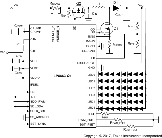
简化原理图
